


The following topics are discussed:
- 9.2.3.1. Creating an Axial Fan Blade
- 9.2.3.2. Initial Design Parameters - Axial Fan Blade
- 9.2.3.3. Initial Angle/Thickness Parameters
- 9.2.3.4. Optimizing the Meridional View
- 9.2.3.5. Define the Inlet and Outlet Sections
- 9.2.3.6. Define the Hub-Shroud Profile at the Leading Edge
- 9.2.3.7. Adjust the Blade Angles at the Shroud in the Angle View
- 9.2.3.8. Adjusting Blade Profiles at Mid-span Locations
- 9.2.3.9. Adjusting the Hub Blade Angles
- 9.2.3.10. Define the Blade Thickness Profile
- 9.2.3.11. Prescribe the Leading/Trailing Edge Ellipse
- 9.2.3.12. Saving Your Model
The following procedure can be followed as an example of using BladeGen to create an Axial Fan blade from start to finish.
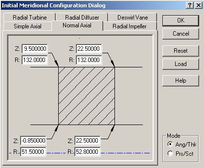
BladeGen allows the user to create a blade system from scratch, using one of six standard initial configuration types. For this example, a Normal Axial template is used.
Select the File | New | BladeGen Model menu command or
 toolbar button which will display the Initial Meridional Configuration Dialog (shown in Figure 9.82: Initial Meridional Configuration Dialog).
Select the Normal Axial tab
Enter the parameters for the initial blade layout as shown in Figure 9.82: Initial Meridional Configuration Dialog.
Be sure to select Ang/Thk mode in the bottom right corner
Press Enter or select the OK button to continue
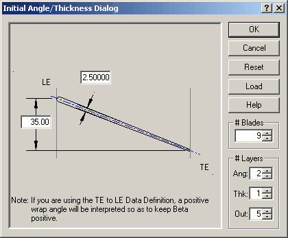
Using Figure 9.83: Initial Angle/Thickness Dialog, the initial blade parameters are completed:
Enter the nominal wrap angle of 35 degrees, thickness of 2.5 and 9 blades.
Press Enter or select the OK button to display the BladeGen Window.
The most critical operation in the meridional view is to define the shape of the hub and shroud curve. The endpoints for these curves were specified when Initial Design Parameters were entered. In this example, we will set the leading edge profile as well as adjust the hub and should positions for both the inlet and outlet.
The following topics are discussed:
The hub and shroud definitions up and downstream of the blade can be defined when the user performs a CFD analysis on the proposed design or to simply have the BladeGen hub and shroud geometry more completely represent the final design. To set the position of the inlet and outlet points:
Double click the shroud inlet point at the top left of the meridional view
The Point Location Dialog will open. The Horizontal value is the Axial location (Z co-ordinate) and the Vertical value represents the Radius
Enter -47.5 and 132 for the horizontal and vertical values. Click OK.
Double click the hub inlet point (bottom left corner) and enter -47.5 and 30 for the horizontal and vertical values. Click OK.
Double click the hub outlet point (bottom right corner) and enter 70 and 52.8 for the horizontal and vertical values. Click OK .
Double click the shroud outlet point (top right corner) and enter 70 and 132 for the horizontal and vertical values. Click OK.
After adjusting the inlet and outlet points, the hub upstream of the blade is a piece-wise linear curve at an abrupt angle. To improve the profile of the hub, this curve will be converted to a more smoothly contoured shape.
Click the hub curve in the inlet section
Right-click the mouse and select Convert Points to.. Spline Curve Points…
In the Point Count Dialog, enter 3 points and select OK.
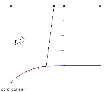
Left-click and drag the resulting control point to make a smooth hub profile. Your Meridional view should now look as shown in Figure 9.84: Meridional View with Smooth Hub Profile.
If you would like more practice, repeat this procedure on the Hub curve at the base of the blade.
At this point, the leading and trailing edges are also piecewise linear curves. Convert the leading edge to a 3 point spline curve and apply a slightly curved profile. Refer to Adjust the Inlet Hub Curve if you need to be reminded of the exact procedure to perform this operation. Place the middle control point at an approximate horizontal and vertical value of 1.5 and 98 (you can double-click the control point to enter specific values if you wish).
The following topics are discussed:
The meridional profile is now defined and the Blade angles can be set. In the Angle View, the active layer is indicated by a red dot in the layer column on the right-hand side. Make the Shroud layer active by selecting the black dot at the top of the layer column. It will turn red and the Shroud is now active.
In this example, we will define the Beta profile at the hub and shroud and also at a new layer located at span=0.6. First, the shroud will be adjusted. The blade angles can now be defined as follows:
Right-click in the Angle view and select Beta Definition
Right-click the mouse a second time in the Angle view and select Convert Points to.. Spline Curve Points…
In the Point Count Dialog, enter 2 points and select OK. This procedure has converted the Beta definition line (colored cyan) to a linear segment
Double-click the beta curve at the leading edge (left-hand side) and enter a vertical Dimension of 83 degrees. Select OK
Double-click the beta curve at the trailing edge (right-hand side) and enter a vertical Dimension of 61 degrees. Select OK
You can also move the points graphically by clicking and dragging a point with the left mouse button.
The following topics are discussed:
It is often desirable to control the blade shape at more than just the hub and shroud locations. To control the blade profiles at more locations, additional layers can be generated. In this example, an additional layer will be generated at a span location of 0.6.
Right-click in the Angle view and select Layer Control.
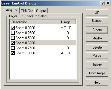
In the Layer Control Dialog, select Create.
In the Layer Dialog, enter a span value of 0.6 and select OK.
The Layer Control Dialog will now look like Figure 9.85: Layer Control Dialog. Note that the Span 0.6 layer is checked, which indicates that the Angle information can be adjusted at this layer. Click OK.
Make the new layer active by selecting the new black dot at the mid-span location of the layer column. After you have selected it, the dot will turn red. Repeat the procedure described in Adjusting the Shroud Blade Angles using a leading edge Beta value of 80° and a trailing edge value of 57°.
Make the Hub layer active by selecting the black dot at the bottom of the layer column. After you have selected it, the dot will turn red. Repeat the procedure in Adjusting the Shroud Blade Angles using a leading edge Beta value of 67° and a trailing edge value of 42°.
The following topics are discussed:
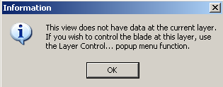
By default, BladeGen assumes that the blade thickness profile is uniform from hub to shroud. If you try to make some thickness modifications at any layer other than the hub a warning message as shown in appears.
To change this setting and allow for control of the thickness profile at multiple layers, we need to adjust the layer information:
Right-click in the Thickness view and select Layer Control…
In the Layer Control Dialog, check the box beside the layer at Span: 1.000 and Span: 0.600.
Select OK.
At the Shroud Layer, convert the curve to a 3 point spline. See Adjust the Inlet Hub Curve if you need specific instructions.
Set the Leading edge thickness to 2mm by double-clicking the leading edge point and entering a thickness of 2mm
Set the Trailing edge thickness to 0.875mm.
Adjust the middle point to make a nice arc between the leading and trailing edge points.
Click on the black dot in the middle of the Layer Column in the Thickness view to make the span 0.6 layer active.
Convert the Thickness curve to a spline with 5 Control Points.
Set the Leading Edge to 3.0mm thickness and trailing edge to 0.875mm
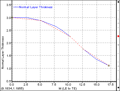
Adjust the 3 internal control points on the curve to make a slight ‘S’ shape as shown in Figure 9.87: Span 0.6 Thickness Profile.
Repeat the procedure outlined in Define the Blade Thickness at Span 0.6 .
Set the Leading edge thickness to 4mm and the trailing edge thickness to 1.25mm.
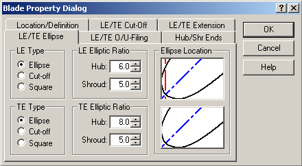
Select Blade | Properties menu commands or the ![]() toolbar button located on the left hand side of the BladeGen window to set the blade properties. Set the Leading Edge/Trailing Edge Ellipse tab; adjust the values as shown in Figure 9.88: LE/TE Ellipse Settings. All other values can remain unchanged.
toolbar button located on the left hand side of the BladeGen window to set the blade properties. Set the Leading Edge/Trailing Edge Ellipse tab; adjust the values as shown in Figure 9.88: LE/TE Ellipse Settings. All other values can remain unchanged.
Upon exiting BladeGen, the blade model is automatically saved to a file associated with the Workbench project. You must save the project before closing it in order to retain the project files. You can save the project from the Workbench interface as usual. You will be prompted for a project name if you have not previously saved the project. The File | Save menu command (Save ![]() toolbar button) can function as an alternative way to save the project; see Saving a Blade Model for details.
toolbar button) can function as an alternative way to save the project; see Saving a Blade Model for details.