


System Coupling supports the creation of interfaces and data transfers between source and target models with different orientations. In a coupled analysis involving models with different orientations, the participant geometries must be aligned closely enough to allow for accurate mapping between the sides of the coupling interface (for example, the rotor and stator in an electric motor simulation are in the same relative position).
To move the geometries into the same reference orientation, use System Coupling's reference frame functionality to define reference frames and transformations in the Library and then apply the transformations to one or more coupling interface sides.
The global reference frame is the base system for the coupled analysis — that is, all transformations in the analysis are performed relative to this initial reference frame.
Multiple levels of nested reference frames may be created. Additional frames may be nested under these, allowing for multiple levels of parent-child relationships.
When defining reference frames:
Reference frames and transformations must be defined prior to analysis initialization. If a modified after initialization, then the changes will not be reflected in the analysis.
Each reference frame must have at least one transformation defined for it.
Note: Rotation transformations have a default unit of radians.
Each reference frame should be exercised in the analysis, either defined for a coupling interface side, used as a parent reference frame, or used in an instancing object.
When ReferenceFrame.Option is set to
ByTransformation, each transformation defined must be added to the reference frame's TransformationOrder list.
Note: When postprocessing coupling results in EnSight, a coupling region can be shown in only one orientation. If a region is involved in multiple coupling interfaces with dissimilar transformations, then it is shown in the GlobalReferenceFrame. To avoid region-orientation disparities in postprocessing output, Ansys recommends that you set up the analysis such that participant regions are transformed into consistent reference frames. For example, you might define the reference frame orientation of each coupling interface such that the geometries are in their actual real-world physical orientation.
For more information, see:
You can add reference frames using either the GUI or the CLI. Using the steps indicated below, you may create multiple reference frames as needed, optionally using the ParentReferenceFrame setting to create a hierarchy of nested frames.
Note: Reference frames are not available if at least one side of an interface is an FMU participant.
When you add the first reference frame object, the Library singleton is added to the data model (if it does not already exist), with the new ReferenceFrame object defined beneath it.
For more detailed information on reference frame definition requirements, see the ReferenceFrame data model object and the AddReferenceFrame() command in the System Coupling Settings and Commands Reference documentation.
- Adding a Reference Frame in the GUI
Perform one of the following actions:
From the Menu Bar, select > .
In the Outline tree, right-click the Setup branch and select Add Reference Frame.
The Reference Frame branch is added to the Library branch, with the new reference frame defined underneath it.
Tip: Once the Reference Frame branch exists, you may add new reference frames by right-clicking it and selecting Add.
Click the reference frame object.
Corresponding settings are shown in the Properties pane below.
Optionally, you may set a parent frame for the added reference frame.
The Parent Reference Frame setting defaults to GlobalReferenceFrame. If other valid reference frames have been defined, you may select one from the drop-down menu.
- Adding a Reference Frame in the CLI
Run the AddReferenceFrame() command. By default, the frame is created as a child of the global reference frame.
Optionally, you can use the ParentReferenceFrame argument to specify the name of a valid reference frame that will be parent to the frame created.
AddReferenceFrame(ParentReferenceFrame = 'Frame-1')

'Frame-2'
When the command is run, the ReferenceFrame object is defined under the Library singleton.
Ensure that each reference frame added has at least one transformation defined for it and is exercised in the analysis.
Note:
By default, Option is set to
ByTransformation.The TransformationOrder setting is available when Option is set to
ByTransformation. This setting is blank when the reference frame is first added. It is automatically populated when transformations are defined by using the Add Transformation GUI option or running the AddTransformation() command. Transformations are listed in the order they are added. You may edit this list if transformations are not added in the order they should be executed.
When ReferenceFrame | Option is set to ByTransformation, can add transformations using either the GUI or the CLI. Multiple transformations can be added to a reference frame. When possible, transformations should be added to a reference frame in the order they are to be executed in.
When you add the Transformation object, it is defined under the parent ReferenceFrame object.
Additional arguments are required to define each type of transformation. For details on the arguments needed for each transformation type, see the Transformation data model object and the AddTransformation() command in the System Coupling Settings and Commands Reference documentation.
- Adding a Transformation in the GUI
In the Outline tree under Library, right-click the reference frame to which the transformation will be added and select Add Rotation or Add Translation.
Note: Rotation transformations have a default unit of radians.
The Transformation branch is added to the tree, with the new transformation defined underneath it.
Note: The transformation type cannot be changed for transformation objects added in the GUI.
Tip: Once the Transformation branch exists, you may add new transformations by right-clicking it and selecting Add Rotation or Add Translation.
Click the transformation object.
Settings corresponding to the transformation type are shown in the Properties pane below.
Set the additional parameters needed to define the specified transformation type.
- Adding a Transformation in the CLI
Run the AddTransformation() command, using the required ReferenceFrame argument to specify the frame to which the transform will be added, the TransformationType argument to specify the type of transformation (Translation or Rotation), and any additional arguments needed to define the specified transform type.
Note: Rotation transformations have a default unit of radians.
AddTransformation(
	ReferenceFrame='Frame-1',
	TransformationType='Rotation',
	Axis='XAxis',
	Angle='45 [degrees]')

'Rotation-1'
When the command is run, the Transformation object container is defined under the parent reference frame object.
If participant models are misaligned, for cases with surface-to-surface mapping you can use System Coupling's automatic interface alignment feature instead of applying transformations manually. Automatic alignment transformations can be applied to one or both sides of an interface.
To enable auto-alignment, set the Library.ReferenceFrame.Option setting to Automatic.
When automatic alignment is enabled, System Coupling uses rigid-body motion (translation and rotation without any bending or stretching) to align the source and target geometries automatically, moving the surfaces as rigid bodies until the sides of the interface match. Source-side transformations are always applied first.
Note that automatically defined transformations can be applied only once. If more
than one interface must be automatically aligned or a single interface requires
multiple automatic alignments, then you must create more than one
ReferenceFrame objects with Option set to
Automatic.
If there is a point that is duplicated in multiple instances, automatic alignment may not work, especially if the total number of points is relatively small.
Geometries with axial symmetry cannot be fully aligned, but may be partially aligned - specifically, the centroid and normal axes can be aligned.
Automatic alignment for point cloud to volume, surface, or point cloud is available when beta features are activated.
If the geometries are significantly misaligned, you may need to apply one or more "manual" transformations (ones defined using the ReferenceFrame.Option.ByTransformation option) in conjunction with transformations defined using auto-alignment. For example, a large enough difference between the interfaces could cause auto-alignment to align them incorrectly (backward or upside down). It may be necessary to pre-apply a manual rotation so that the geometries align with the correct orientation..
To chain transformations, you would perform a manually defined transformation before a transformation defined using automatic alignment. If further adjustment is needed, then you could follow the automatic alignment transformation with another manually defined transformation, as follows:
Note that you may add multiple transformations of either type in sequence, as needed. For example, you could add several manually defined transformations either before or after the automatic transformation, and you could also add several automatic alignment transformations in a row.
For information on chaining transformations, see:
Note: When supplying a parent ReferenceFrame to a
ReferenceFrame with Option set to
Automatic, setting
the parent ReferenceFrame.Transformation.Option to
UserDefined yields
an incorrect transformation.
To avoid this issue, set the parent reference frame's
Option to XAxis, YAxis, or ZAxis.
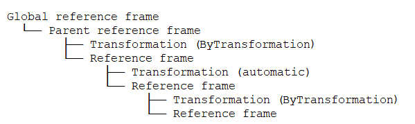
Define the first transformation created via the
ByTransformationoption.Under Setup, right-click Library and select Add Reference Frame.
The Reference Frame branch is added, with Frame-1 defined beneath it.
Right-click Frame-1 and select one of the Add Transformation options.
A transformation is added.
Use the Transformation Order setting to specify the order in which the transformation will be executed.
Define the automatic alignment.
Right-click the Reference Frame branch and select Add.
Frame-2 is added.
For Frame-2, set the following properties:
Set the Option to Automatic.
Set Parent Reference Frame to Frame-1.
Define another transformation created via the
ByTransformationoption.Right-click the Reference Frame branch and select Add.
Frame-3 is added.
For Frame-3, set Parent Reference Frame to Frame-2.
Right-click Frame-3 and select one of the Add Transformation options.
A transformation is added.
Use the Transformation Order setting to specify the order in which the transformation will be executed.
frame1 = DatamodelRoot().Library.ReferenceFrame["Frame-1"]
frame1.Option = "ByTransformation"
frame1.ParentReferenceFrame = "GlobalReferenceFrame"
t1 = frame1.Transformation["Transformation-1"]
t1.Option = "Rotation"
t1.Axis = "XAxis"
t1.Angle = "45 [deg]"
frame1.TransformationOrder = ["Transformation-1"]

frame2 = DatamodelRoot().Library.ReferenceFrame["Frame-2"]
frame2.Option = "Automatic"
frame2.ParentReferenceFrame = "Frame-1"

frame3 = DatamodelRoot().Library.ReferenceFrame["Frame-3"]
frame3.Option = "ByTransformation"
frame3.ParentReferenceFrame = "Frame-2"
t2 = frame3.Transformation["Transformation-1"]
t2.Option = "Translation"
t2.Vector = [0.0, 0.0, 0.5]
frame3.TransformationOrder = ["Transformation-1"]
Each side of a coupling interface has a ReferenceFrame setting that allows you to specify the reference frame from which any geometry transformations will be performed. By default, it is set to the global reference frame. If other reference frames have been defined, they are populated to and can be selected from the setting's drop-down menu.
Note: In most cases, a reference frame does not need to be set for both the interface side and the instancing object associated with that side. This could indicate an error in the interface side setup.
If transformations were not added to the frame in the correct order of execution and ReferenceFrame.Option is set to ByTransformation, you can reorder the list for the frame's TransformationOrder setting.
When the analysis is solved, reference frames are executed hierarchically from the top down, with parent frames before child frames. Within a given reference frame, transformations are executed in the order specified by the TransformationOrder setting.
The composite transformation is printed in the Reference Frame and Instancing Information section of the Transcript. When the solve is complete, it can be queried using the GetTransformation() command.