Ansys DesignModeler topics:
Face Geometry Transfer
Faces without associated geometry may be generated when attaching to a CAD system or when importing from a file. This may occur for all CAD systems or file formats with the exception of Parasolid (*.x_t, *.xmt_txt, *.x_b, *.xmt_bin), IGES (*.igs, *.iges), STEP (*.stp, *.step), Monte Carlo N-Particle (*.mcnp), Ansys BladeGen (.bgd) and Ansys DesignModeler (.agdb). Loading geometry into the Ansys DesignModeler application may result in a greater frequency of occurrence of such faces than when loading geometry into the Ansys Mechanical application.
The Ansys Mechanical application will fail to construct a part when an associated face without geometry is found and will report an error.
The Ansys DesignModeler application will construct parts excluding faces without geometry. A solid or surface body in the CAD system or file with such faces detected will result in surface bodies being constructed. The constructed surface bodies are generated from the faces with geometry and will consist of the faces that are connected by shared edges. If the Line Bodies property is set to "Yes" (enabling import of line bodies), then line bodies will be constructed from edges only belonging to faces without geometry that have been removed. A warning message indicating a partial import will be generated for all parts that have been imported in Ansys DesignModeler with faces without geometry having been removed.
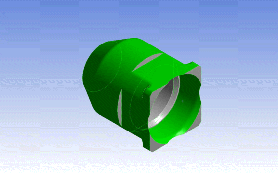
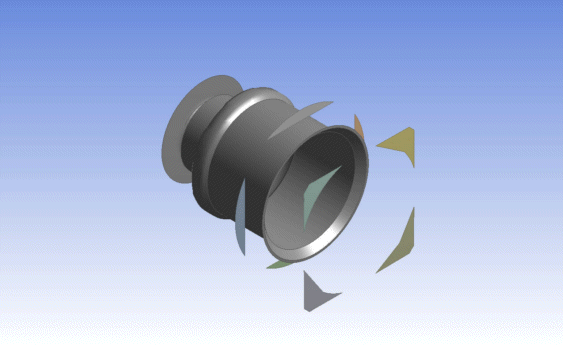
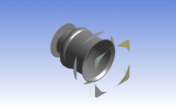
Example 1: Face Geometry Transfer Scenarios
 Shown above is a body with two faces highlighted for which geometry is not constructed during transfer. |
 Shown above is a body in the Ansys DesignModeler DesignModelerapplication where two faces are not being transferred. |
 Shown above is a body in the Ansys DesignModeler application where two faces are not being transferred and the Line Bodies property is set to yes. |
The Ansys Mechanical application supports the DesignModeler application as both a pseudo-reader and a plug-in.
Attaching Geometry
Unlike other CAD systems, filtering of bodies during import from DesignModeler to the Ansys Mechanical application is not done through import options. All unsuppressed bodies in Ansys DesignModeler will be transferred to the Ansys Mechanical application.
Any planes in the Ansys DesignModeler application that are flagged to be exported will appear in the Ansys Mechanical application as a local Cartesian coordinate system upon attachment and will be inserted into the Ansys Mechanical application tree. The automatic creation of the coordinate system occurs during attachment and is updated during a refresh.
Any enclosures defined with a model in the Ansys DesignModeler application will be retained upon attaching. Once in the Ansys Mechanical application, the enclosure has the following characteristics:
A transparency value of 0.1 (subdued) is assigned to the enclosure to assist in the visualization of the model items inside the enclosure.
A default field material of Air is automatically assigned to the enclosure. You can change the default field material in Engineering Data. A field material is used in any open domain simulation where an artificial boundary such as an enclosure is used to surround the model. Any fields extending from the model to the edges of the enclosure experience the field material.
You can control whether Coordinate Systems and Enclosures that are created in the DesignModeler application files are imported in the Ansys Mechanical application by checking the Advanced Geometry Options, specifically:
Import Coordinate Systems
Enclosure and Symmetry Processing
Parts and Assemblies
The Ansys DesignModeler application does not support assemblies, but does allow you to create and import multiple bodies. If you import a model made up of independent multiple bodies, they will be imported into the Ansys Mechanical application as individual bodies using contact elements.
If you import a model that has multibody parts (that is, parts that include multiple bodies within them as a group), then the model will be imported using shared topology so that no contact is required and meshes on the volume interfaces will match.
The Ansys DesignModeler application parameters are all set at the model level. Since Ansys DesignModeler publishes its own parameters to the project schematic, its parameters are not displayed in the Ansys Mechanical application under the Geometry branch.
For line body properties that appear in the Ansys Mechanical application, the values shown are for the raw cross section, that is, the offset type and/or user defined offset from the Ansys DesignModeler application's body properties have no bearing on the calculations shown in the Ansys Mechanical application. They are taken directly from the cross section without applying any offset.
Surface body thicknesses and material properties are transferred from the Ansys DesignModeler application to the Ansys Mechanical application.
Notations
If you are using the Ansys DesignModeler application as a pseudo-reader, the Ansys Mechanical application will maintain associativity with the Ansys DesignModeler application model. If you modify parameters in the Ansys Mechanical application, the Ansys DesignModeler application model will change upon update.
Models that have fatal errors when regenerating in the Ansys DesignModeler application will not be able to be imported via the reader mode into the Ansys Mechanical application. Before importing, first open the model in the Ansys DesignModeler application to resolve the regeneration failures.
When the Ansys Mechanical application is first attached to an Ansys DesignModeler application, the Fluid/Solid property associated with all DesignModeler solid bodies will be transferred to a Material Assignment property for all associated solid bodies in the Mechanical application. However, when refreshing all data in the Mechanical application, following an initial attach to DesignModeler, the Mechanical application Material Assignment property for solid bodies will not be updated further.
When an Ansys DesignModeler model has multiple material definitions with the same name, only one of these will be transferred to the Mechanical application.
Length Unit
The Ansys Mechanical application automatically sets the length unit to match the units used in the Ansys Workbench project itself, not the length unit of the model in the Ansys DesignModeler.


