


Nastran Custom Integration provides 2 types of nodes. The first one, NASTRAN node, provides full functionality (input, solver, output). The second one, NASTRAN Output node, is a simplified version that can be used as a pure output node.
The NASTRAN node integrates a Nastran model into the optiSLang workflow. The integration of the Nastran model provides the following functionality:
Input integration (extracting of input parameters from the Nastran input files and setting updated values for the specified parameters to these files).
Solver integration (solving the Nastran model in batch).
Output integration (extracting updated output parameters from the Nastran output files).
The implementation is independent from a given Nastran model. You provide a prepared and solved Nastran model with input files (.bdf, .dat, .nas, .inp) and result files (.h5, .hdf5, or .op2). The supported parameter types are automatically detected, and you can select them as input or output parameters. You do not need to do any additional manual work, for example searching for parameters in input or output files, defining of the parameter locations, and so on.
The NASTRAN Output node serves for cases when it is only requested to read the output file from NASTRAN and the input file is not available. See the NASTRAN Output node section for more information.
Setup
There are two ways to build variational analysis with the Nastran integration.
Using the Solver wizard:
Drop the Solver wizard onto the Scenery pane to set up new process chain, or onto an existing subsystem to extend a solver chain, as described in Solver Wizard.
From the list of solvers, select .
Select your Nastran input file (.bdf, .dat, .nas, .inp) and click .
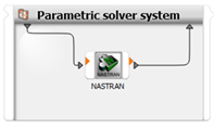
A parametric system containing a NASTRAN node is created automatically.
Double-click the NASTRAN node to open its edit dialog box.
The inputs and outputs of the Nastran model are extracted automatically, inputs from the Nastran input file (and optionally from files included using “INCLUDE” statement with relative path to the input file; see the Parameters section) and outputs from the corresponding Nastran binary output file (HDF5 format by default).
Define the parameters and responses using the inputs and outputs of the Nastran model.
Manual setup:
Drop the Parametric System system (located in > > onto the Scenery pane to set up new process chain or onto an existing subsystem to extend a solver chain.
Drop the NASTRAN node (located in > > onto the Parametric System created in the previous step.
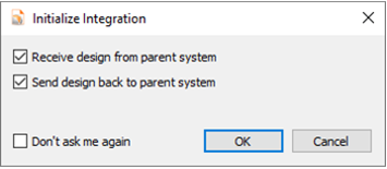
In the Initialize Integration dialog box, click .
A parametric system containing a NASTRAN node is created automatically.
Double-click the NASTRAN node to open its edit dialog box..
To select an input file, click
 .
.Navigate to your Nastran input file (.bdf, .dat, .nas, .inp), select it, and click .
The inputs and outputs of the Nastran model are extracted automatically, inputs from the Nastran input file (and optionally from files included using “INCLUDE” statement with relative path to the input file; see the Parameters section) and outputs from the corresponding Nastran binary output file (HDF5 format by default).
Define the parameters and responses using the inputs and outputs of the Nastran model.
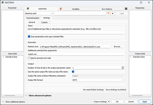
Every NASTRAN node serves as an input, solver, and output node by default, using the settings shown in the following image.
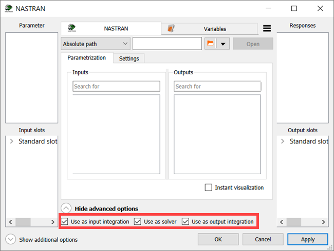
However, different workflows can be created using separate nodes as the input integration, solver, output integration, or their combinations. In all cases, even when set up as an output integration node, you must select the Nastran input file as the project file of the node. The output file will be identified automatically according to the settings. Alternatively, the NASTRAN Output node may be used instead of NASTRAN node with output-only setting (see the NASTRAN Output node section for more information).
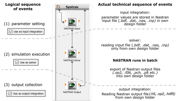
The logical sequence of events and the actual technical sequence of events are described as follows:
Combining nodes with different functionality allows you to create complex custom workflows that can be extended by other integrations provided by optiSLang. A typical example is shown in the following image.
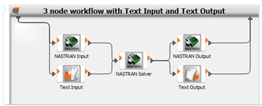
The example workflow consists of two input nodes, one solver node and two output nodes.
The NASTRAN Input node can be used for reading supported cards provided in the Nastran fixed field or free field format. Small and large format of both variants is supported. Cards unsupported by default can be defined in the settings. Alternatively, input parameters of the unsupported cards or cards with unsupported formatting can be defined separately by the Text Input node, as shown in the previous image.
Large Nastran models can produce big output binary files, and their processing can be time consuming. To increase performance and to reduce amount of data, export only the required Nastran results to additional text files which can be processed by the Text Output node, as shown in the previous image.
Parameters
The list of supported cards and their parameters are shown in the following table:
| Card | Parameters |
|---|---|
| FORCE | F, N1, N2, N3 |
| GRID | X1, X2, X3 |
| LOAD | S, S1, S2, S3, S4, S5, S6, S7, S8, S9, S10, S11, S12, S13, S14, S15, S16, S17, S18, S19, S20 |
| MAT1 | E, G, NU, RHO |
| MAT8 | E1, E2, NU12, G12, G1Z, G2Z, RHO |
| MOMENT | M, N1, N2, N3 |
| PBAR | A, I1, I2, J, NSM, I12 |
| PBEAM | A(A), I1(A), I2(A), I12(A), J(A), NSM(A) |
| PCOMP | NSM, T1, THETA1, T2, THETA2, T3, THETA3, T4, THETA4, T5, THETA5, T6, THETA6, T7, THETA7, T8, THETA8, T9, THETA9, T10, THETA10, T11, THETA11, T12, THETA12, T13, THETA13, T14, THETA14, T15, THETA15, T16, THETA16, T17, THETA17, T18, THETA18, T19, THETA19, T20, THETA20 |
| PELAS | K1, GE1, S1, K2, GE2, S2 |
| PLOAD2 | P |
| PLOAD4 | P1, P2, P3, P4 |
| PLOADX1 | PA, PB |
| PROD | A, J, C, NSM |
| PSHELL | T, NSM |
| PSOLID | MID, CORDM |
| SPCD | D1, D2 |
| TEMP | T1, T2, T3 |
If unsupported cards and parameters are required you can create custom cards.
In the optiSLang user interface, detected parameters are organized in the tree structure with the following hierarchy:
Input file
Card name
Parameter name
List of detected parameters
Each parameter has the following attributes:
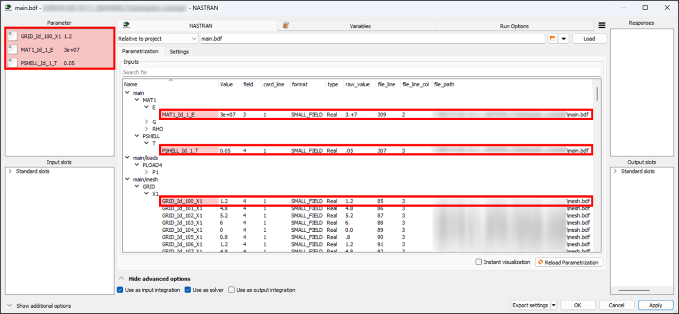
Name: Consists of the card name, card ID and the parameter name. If the parameter name already exists, the file line number is added to the end of the name to ensure parameter name uniqueness.
Value: Detected parameter value.
field: Card column number where the parameter is located. The value is defined for the card in the small, fixed field format. For more details, see the Nastran help.
card_line: Card row number where the parameter is located. The value is defined for the card in the small, fixed field format. For more details, see the Nastran help.
format: Card format.
type: Data type of the value.
raw_value: String representation of the detected card field.
file_line: File line number where the parameter is located.
file_line_col : Column where the parameter is located.
file_path: Path to the file from which the parameter is loaded.
The following image shows an example of parameters detected by the NASTRAN node.
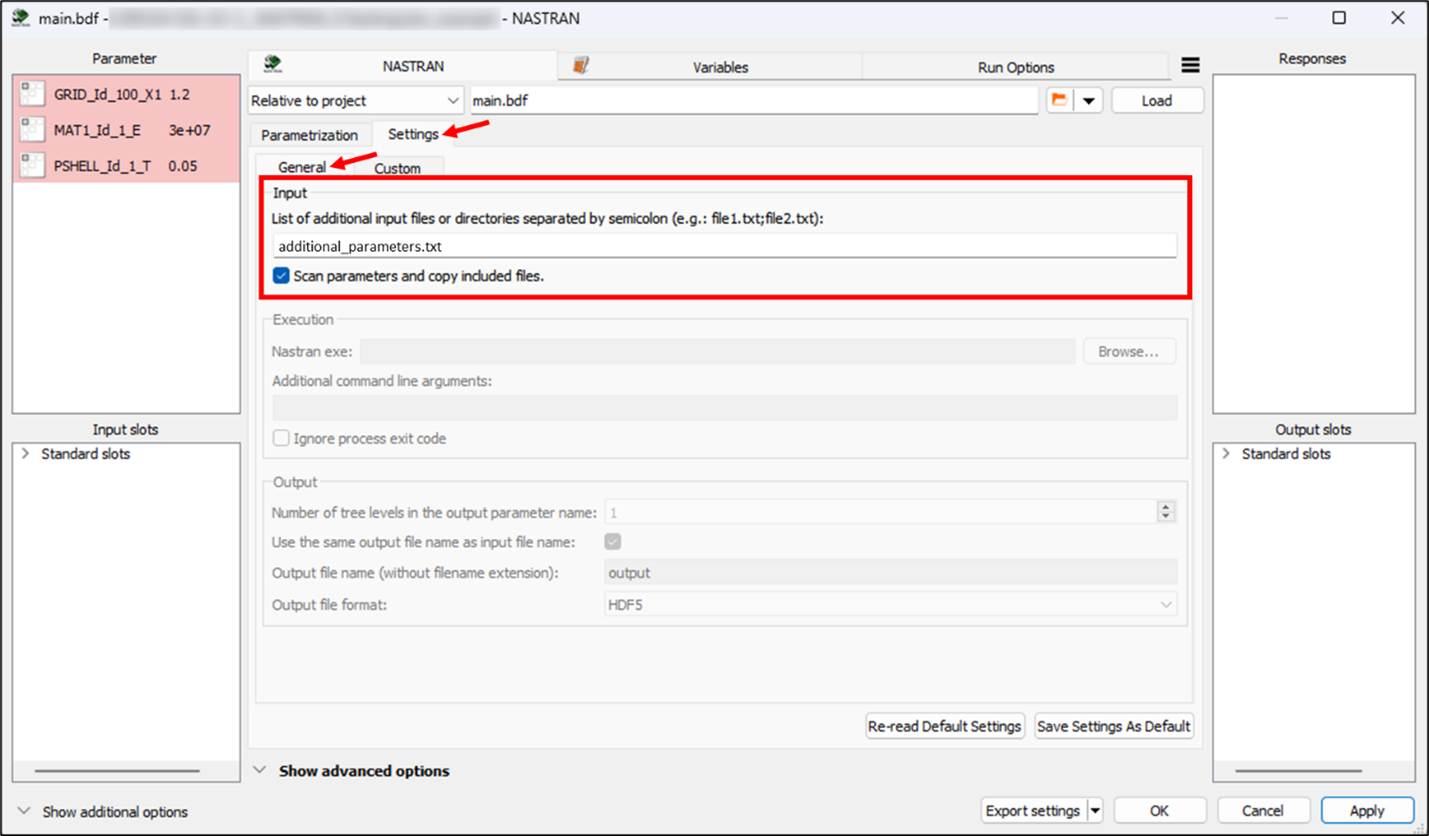
By default, the project file of the integration (with modified parameters) and included files with relative path to the main file are copied into the optiSLang working directory. If the included files are not requested to be accessible for parametrization and automatically copied, disable checkbox "Scan parameters and copy included files" in the settings. However, additional files or directories may be required to run the solution properly. These files or directories can be specified in the settings. In the following example, the additional_parameters.txt file is defined as an additional input file and is automatically copied to the working directory.
Unsupported cards and parameters can be added in the settings.
Responses
There are two types of Nastran binary output formats supported by the integration:
HDF5 format (.h5, .hdf5) (preferred)
OP2 format (.op2) (partially supported)
Default binary output format is HDF5 (.h5). You can change the output format in > > > . Outputs are automatically extracted and their values can be used as responses or as internal variables and further processed using standard optiSLang functionality as scalar responses, xy-data, or signals.
The output binary file is searched in the directory where the project file of integration is located. The name and the extension of the output binary file is determined by the name of the project file and the output file format by default. This behavior can be changed in the settings. If the output binary file is found, the output parameters are automatically extracted. The output file does not need to exist. In that case, no output parameters are extracted.
To avoid processing the large amount of data stored in the Nastran binary files, text files with customized Nastran output can be processed instead of the binary files. The Nastran solver typically provides text files (.f06, .pch, xy-data, and so on) that only store results needed for response definition. These text files are not directly supported by the integration; however, they can be processed by the Text Output node. These files can be found in the optiSLang working directory for each design.
Solver
You can specify the executable of the Nastran solver in the settings.
The Nastran executable allows you to specify additional arguments to set up the solution process. These arguments can be specified in the settings. The default value is batch=no, which is required on Linux systems.
Parallelization
Parallelization is supported.
Settings
Nastran settings are divided into two sections:
General
Custom
General Settings
General settings are related to the input, execution, and output.
| Field | Description |
|---|---|
| Input | |
| List of additional input files or directories | The specified files or directories are copied into the working directory before the solution is run. They must be located in the project file directory of the integration. Files or directories in the list must be separated by semicolons, for example file1.txt;directory1;file2.txt;file3.ext. |
| Scan parameters and copy included files | Specifies whether the included files (using INCLUDE statement in the bulk sections of the input files) relative to the main input file should be scanned for parameters and automatically copied into the working directory before the solution. |
| Execution | |
| Nastran exe | Path to the Nastran executable. |
| Additional command line arguments | Additional command line arguments used to execute the Nastran solver. |
| Number of tree levels in the output parameter name |
The number of nodes in the tree hierarchy whose names are appended to the original parameter name to make it unique. optiSLang requires parameter names to be unique. If parameter names are the same, an additional number is automatically added to the end of the second parameter name. To avoid these numbers, increase the value of this setting. As a result, the parameter names will contain the name of their next ancestor node, so there is less chance that some parameter names will be the same. Note: Parameters with updated names do not correspond to the previous ones. Therefore, if a definition with old parameters (the same parameters with the old names) exists, it must be redefined with new parameters (the same parameters with the new names). |
| Use the same output file name as project file name | When selected, the output file with same name as the project file is used to extract output parameters. The file extension is not considered. When cleared, the output file name must be specified. |
| Output file name | Name of the file used to extract output parameters. The file name must be set without the file extension. |
| Output file format | Format of the file used to extract output parameters. |
Custom Settings
These settings allow you to define additional cards and read their parameters from the input files (.bdf, .dat, .nas, .inp). Currently, not all cards and parameters are initially supported. Therefore, these settings remove the restriction on initially supported cards and parameters.
The custom settings are divided into two parts. The first part is related to the custom cards. The list of custom cards is shown in the table, and it can be modified by adding new cards or editing or deleting current ones. The second part is related to the list of custom parameters of selected custom card in the first part. The list of custom parameters is shown in the table, and it can be modified by adding new parameters or editing or deleting current ones.
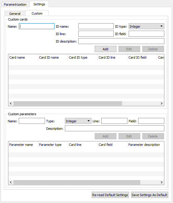
To define additional supported parameters, the custom card to which the parameter belongs must be defined first. To define a custom card, specify the following values:
| Field | Description |
|---|---|
| Name | Name of the custom card. |
| ID name | Name of the parameter which uniquely identifies the card. |
| ID type | Data type of the parameter which uniquely identifies the card. |
| ID line | Line number of the card specification where the parameter that uniquely identifies the card is defined. It is assumed that the card specification is in the small field fixed format and the line number starts from 1. |
| ID field | Column number of the card specification where the parameter that uniquely identifies the card is defined. It is assumed that the card specification is in the small field fixed format and the field (column) number starts from 1. |
| ID description | Description of the parameter that uniquely identifies the card. This value is optional. |
Once a custom card is defined, you can define its parameters. To define custom parameters, select the custom card to which the parameter belongs and specify the following values:
| Field | Description |
|---|---|
| Name | Name of the custom parameter. |
| Type | Data type of the custom parameter. |
| Line | Line number of the card specification where the parameter is defined. It is assumed that the card specification is in the small field fixed format and the line number starts from 1. |
| Field | Column number of the card specification where the parameter is defined. It is assumed that the card specification is in the small field fixed format and the field (column) number starts from 1. |
| Description | Description of the custom parameter. |
A custom card has higher priority than the card supported by default. In other words, if a card which is supported by default is defined as a custom card, then only the custom definition is considered.
Note: Each time you change a setting, you must click or for it to be saved.
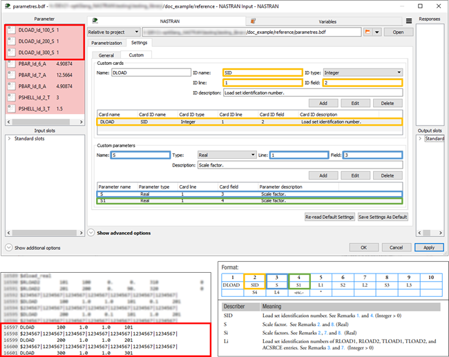
An example of the custom card definition is shown in the images below. The top image shows the custom card settings in the optiSLang environment. The bottom left image shows the part of the input file where the card is located. The bottom right image shows the card specification in the Nastran manual.
In the example, a new custom card named DLOAD is defined. The card has an identification number that corresponds to the parameter SID. The SID parameter has an integer value and is in the first line and second column of the card specification. Note that the card specification is always in the small, fixed field format. Optionally, the parameter description can be defined as it was done in the example.
The custom card DLOAD has defined two parameters, namely S and S1. Both parameters have real values, they are in the first line of the card specification (in the fixed field format), and both are scale factors as defined in the parameter description. The parameter S is in the third column of the card specification and the parameter S1 is in the fourth column.
An arbitrary card and its parameters can be defined using the custom card settings. However, the location of the parameters must be fixed.
Run Options
This node has general Run Options. The number of supported options is individual for each node.
Versions and Requirements
Supported operating systems:
All Windows versions supported by Ansys 2024 R2 and later (Tested on Windows Enterprise ((22H2))
All Linux versions supported by Ansys 2024 R2 and later
Versions:
Tested with NX NASTRAN 2206
Compatible optiSLang version: 2024 R2
See the Supported Integration Versions table for more information
Troubleshooting
The optiSLang logging system provides useful information about the solution process (for more information, see Logging Management).
To get more information from the optiSLang logging system, change the logging
level by setting the ANSYS_OPTISLANG_VERBOSE_LEVEL environment
variable to the following values:
0: Silent (Default)1: Verbose
Nastran custom integration provides standard output and standard error files of the Nastran solver process:
subprocess
_<input file
                                name>
_stdout.txt (standard output)subprocess
_<input file
                                name>
_stderr.txt (standard error)
Detailed information about the solution process can be found in the files generated by the Nastran solver (.log, .f04, .f06).
These files can be found in each design directory (see Project Directory Structure).
To overcome some unexpected issues related to reading of the Nastran input or output files, the Text Input or Text Output node can be used in addition to (instead of) the Nastran node, see Setup.
Best Practices
Ansys recommends using the large field fixed format as it is more accurate.
Ansys recommends avoiding mixing of small and large field formats within one card definition.
Ansys recommends keeping small free field format limited to 8 values per line to prevent exceeding the 80 characters limit.
Ansys recommends using the output data HDF5 file format over the OP2 file format.
Ansys recommends checking whether the input parameters were changed correctly (especially when the custom parameters are used) as versions of Nastran are currently available from several vendors. This can be done by comparing the reference input file with input files located in each design directory.
Limitations
The NASTRAN op2 Format is partially supported. The preferred format for extracting NASTRAN results/outputs is HDF5-Format.
The default value of Additional command line arguments option in the execution settings is set to "batch=no". This value indicates that the Nastran solver process is to be run as a foreground process. On the Linux system, if the value is omitted the Nastran solver process will be run as a background process by default. This may cause problem that the NASTRAN node does not wait the background process to finish but continues immediately to the next processing step.
Version History
Version 1.0.9
Separate NASTRAN Output node was added
Location of NASTRAN node in Modules directory changed from Add-Ins to Integrations.
Updated third-party tools and libraries:
h5py 3.7.0 => h5py 3.9.0
Version 1.0.10
The dependencies were moved to optiSLang python.
Version 1.0.11
Ignore exit code checkbox was added.
Version 1.0.12
Free field format input is supported.
Extension of cards loaded by default (GRID, PSOLID).
"INCLUDE" statement in the bulk sections of the input files can be optionally automatically processed, such files can be parametrized directly from the NASTRAN node
Use environment variable "UGII_NX_NASTRAN" to auto-detect solver.
Updated third-party tools and libraries:
h5py 3.9.0 > h5py 3.10.0
pyNastran 1.3.4 > pyNastran 1.4.0