


To display the integration dialog, add an integration node to the Scenery pane and double-click the node.
| Number | Feature | Description |
|---|---|---|
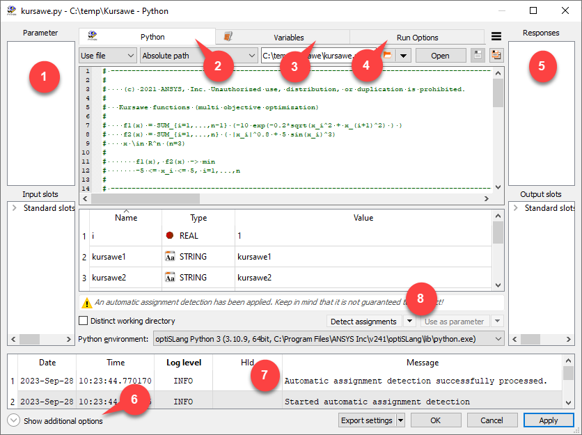
| 1 | Input | Lists all parameter or input slots. For most integrations, these can be added by dragging from the integration specific pane to the input side and dropping on the Parameter or Input slots pane. Some integration dialogs offer buttons instead. Inputs are classified as design entries. When adding a parameter, the parsed value is used as reference value. |
| 2 | Integration specific |
This part of the dialog differs for all integrations. Most integration dialogs consist of a File Browse section to load a corresponding file and an integration specific content pane. This pane is filled with data depending on the file format and the type of integration. For script and common text based integrations, the integration specific pane is a text editor that displays the content of the file. The context menu of the text editor offers specific features only for script integrations.
For script integrations a list of suggestions (input/output candidates) is displayed. Drag and Drop: Suggested variables can be dragged and dropped to use as one of the following.
For some integrations there are (multi-action) buttons to register/add one of the last mentioned items, as well as Shortcuts and the context menu. : Select this check box to create an extra directory in the design directories for calculations. This option is only available for Python, MATLAB, and Excel nodes. |
| 3 | Variables |
Any location can be registered as (internal) variable. This is helpful when defining derived outputs, for example, a signal created from two vectors. All registered variables are listed in a table with an ID, the value type, the evaluated value, integration specific location information and an expression for derived variables. Registration of variables can be applied either by drag and drop or by selecting on the multi-action button (if available). Internal variables can be used to define new derived variables that are needed as output. The Expression cell of a derived variable provides the functionality of the calculator. With the approach of using internal variables and the definition of derived variables directly within the integration, the workaround using slots and calculator to define special responses is unnecessary. Instant visualization is available for variables and provides special features for array-like variables. Vector, signal and matrix elements or the x-axis can be dragged from instant visualization panes and dropped either into the variables table or directly into the calculator dialog of an existing variable. The first option automatically creates a new variable, which is initialized with the corresponding expression. An existing expression can be extended using the second option. Supported types with resulting expressions
The context menu offers the following options:
|
| 4 | Run Options |
List of general options for controlling node runtime execution. The number of supported options is individual for each node.
|
| 5 | Output |
Lists all responses or output slots. For most integrations, these can be added by dragging from the integration specific pane to the output side and dropping on the Response or Output slots pane. All standard slots can be seen when opening the flyout. Manually added slots are displayed directly. |
| 6 | Additional options |
Displays or hides additional options. By default is selected for integration nodes. can be selected as well. |
| 7 | Message log pane | Displays error, information, and warning messages. This pane is only displayed if there are messages to show. |
| 8 | Multi-selection buttons | Allows you to select an action from a list of options, then apply the action by clicking the button. |