


The Solver wizard allows you to set up and extend process chains.
Set up a Process Chain
From the Wizards pane, drag the Solver wizard to the Scenery pane and let it drop.
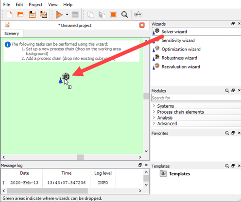
You can also add it into an existing subsystem. The feasible areas where it can be dropped are highlighted green.
The Solver wizard opens.
On the Solver paradigma page, select a solver type.
In the Select input file dialog box, browse to an input file.
Click .
Define the input and output parameters.
The exact steps depend on the selected solver. In general, the Solver wizard consists of three parts which are all connected by design slots:
Input block
All input parameters are listed.
Parametrize block
This block depends on the solver type.
Output block
All output parameter are listed.
If required, on the Parametrize Inputs page, you can modify the parameter type, reference value, range, and other parameter properties.
If shown, on the Criteria page, you can define the optimization criteria.
If shown, on the Solver Process page, you can import a solver call script and define solver process settings.
On the Additional options page, you can create a template from the solver chain. To do so, select the check box, and enter a template name if you do not want to use the default one. You can also change the file path of where the template is saved.
This solver chain is listed in the Templates pane and can be used when reopening optiSLang. The visibility and the default behavior can be controlled using the configuration entries Show create template option and Create template by default.
Click .
You can now run the project, add more systems or nodes to the project, or use additional wizards.
Extend a Process Chain
To edit parameters or add input/output files, From the Wizards pane, drag the Solver wizard to the Scenery pane and let it drop onto an existing process or script actor. Then select from the following options:
You can modify all parameters of the system. Selecting this option is the same as opening the system dialog.
Add and parametrize an input file. Browse for an input file and parametrize parameters that are then added to the system.
Register existing file to be copied. Some processes might need some extra files only for execution but not for parametrization. These can be registered and copied into the design directory.
Connect workflow created file. A system might contain several input files that can be connected to the process node. Select the workflow created input and the input file slot to connect to.
Add and parametrize an output file. Browse for an output file and parametrize responses that are then added to the system.
Register an expected file. Register an output file that is expected after running the process. The file will be checked after running the process to see if this file exists.
Connect as workflow created file. A process might create an output file that can be connected by this option. Select the workflow created output and the output file slot to connect to.