


 The Curve Mesh Setup option allows you to set mesh parameters for curves. This feature is useful for both surface and tetra meshing in controlling mesh size or distribution on surface boundaries. There are several parameters, but in most cases setting the element size is sufficient for meshing.
There are the following methods for setting the Curve Mesh Size:
Figure 295: Curve Mesh Setup – General: This method involves entering the parameter values in the provided fields.
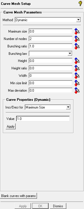
Figure 296: Curve Mesh Setup – Dynamic: This method allows you to select a curve and adjust the values using the mouse buttons.
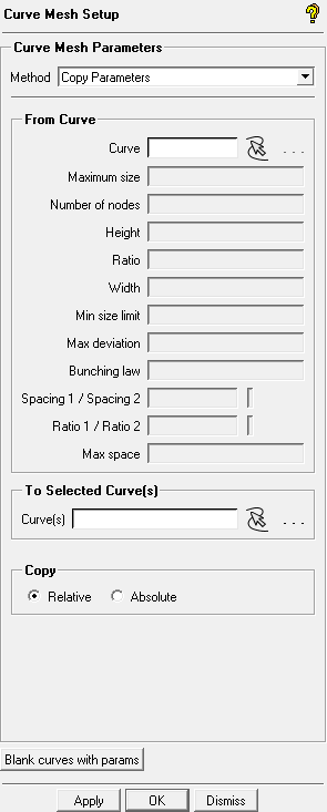
Figure 297: Curve Mesh Setup – Copy Parameters: This method allows you to copy curve mesh parameters to the selected curve(s).
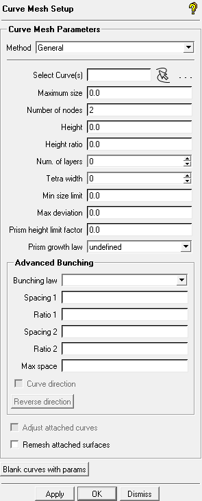
- General
allows you to enter the following parameter values in the respective fields:
- Select Curve(s)
specifies the curves for which mesh parameters are to be defined.
- Maximum size
is the maximum element size for the selected curves. The actual element size will be this value multiplied by the Global Element Scale Factor. The element size can be displayed by right-clicking Curves in the Model tree and selecting Curve Tetra Sizes or Curve Hexa Sizes.
- Number of nodes
is the number of elements for the selected curves. This is an alternative option to setting the element size. The number of elements entered should be more than 2. The node spacing can be displayed by right-clicking Curves in the Model tree and selecting Curve Node Spacing.
- Height
is the height of the first elements, normal to the curve. This value applies to Hexa mesh and Patch Dependent Surface mesh, and can be any positive real number.
- Height Ratio
is an expansion ratio from the first layer of elements on the curve. This ratio will be multiplied by the element height of the previous layer to define the next layer. You can enter any positive real number. This parameter applies to Hexa, Prism mesh, and Patch Dependent Surface mesh.
- Number of layers
is the number of layers to be grown from the surface or curve.
- Tetra width
creates the specified number of tetra layers with element size as specified by the Max size.
- Min size limit
Curve elements will be prevented from being subdivided smaller than this value.
This parameter works only with the Curvature/Proximity Based Refinement option under Global Mesh Size. You can override the global or part setting on selected curves by setting this value smaller than the global setting or part setting, whichever is smaller.. The actual minimum size will be this value multiplied by the Global Element Scale Factor.
- Maximum deviation
is a method of subdivision based on the proximity of the centroid of a tri or quad surface element to the actual geometry. If the distance is greater than this value, the element will automatically split and the new nodes will be projected onto the geometry. The actual distance is the value multiplied by the Global Element Scale Factor.
- Prism height limit factor
is used to create a local maximum aspect ratio for prisms on selected curve(s). A full description is available in Global Prism Settings. If zero, the global or part value is used.
- Prism growth law
is used to specify a local growth law for prisms on selected curve(s). A full description of the available laws is available in Global Prism Settings. If , then the global or part law is used.
- Advanced Bunching
contains options providing more control over the mesh parameters. Refer to Blocking > Pre-Mesh Params > Edge Params > Bunching Laws for more detailed explanation.
- Bunching law
- BiGeometric
This is the default bunching law. The two initial heights and ratios define parabolas in a coordinate system where the number of node points is the X-axis and the cumulative distance along the edge is the Y-axis. The parabolas are truncated where their tangent lines are identical; the spacing is linear between these points. If there are not enough nodal points to form this linear segment, a hyperbolic law is used and the ratios are ignored.
- Biexponential
The Spacing1 and Ratio1 parameters define the distribution from the beginning of the edge to the midpoint of the edge using an Exponential law. Spacing2 and Ratio2 are similarly used to define the distribution from the terminating end of the edge to the midpoint of the edge.
- Curvature
The spacing of the node intervals is calculated according to the curvature of the function defining the distribution.
- Exponential1
The spacing of the ith interval from the beginning of the edge is defined using an exponential function of the Spacing1 and Ratio1 parameters.
- Exponential2
Similar to Exponential1, except that Spacing2 and Ratio2 parameters are used and the distribution starting point is the terminating end of the edge.
- FullCosinus
The spacing of node intervals is calculated using the cosine function. The ends of the edge have the same constraint values for spacing and ratio.
- Geometric1
Spacing1 is used to set the first distance from the starting end of the edge, then the remaining nodes are spaced with a constant growth ratio. Only Spacing1 is specified.
- Geometric2
Similar to Geometric1, except that Spacing2 is used to define the distribution starting from the terminating end of the edge.
- HalfCosinus1
The spacing pattern follows a half cycle of a Cosine function. Distribution begins from the starting point of the edge and the parameters for spacing and ratio differ on either end.
- HalfCosinus2
Similar to HalfCosinus1 in that the parameters for spacing and ratio follow a half cycle of a Cosine function, but distribution starts from the terminating end.
- Hyperbolic
The spacing parameters for each end are used to define a hyperbolic distribution of the nodes along the edge. You can set Spacing1 and Spacing2, and the growth ratios are determined internally.
- Poisson
The spacing of the node intervals is calculated according to a Poisson distribution. Requested values of Spacing1 and Spacing2 are used. Requested values of Ratio1 and Ratio2 are not used directly, but are used to determine if the requested spacing is appropriate. If not, the spacing will be adjusted automatically.
- Uniform
The nodes along the edge are uniformly distributed.
- Spacing
The spacing of the first node from the beginning of the edge (first cell height). When an edge is selected, an arrow appears along the edge. Spacing 1 refers to the parameters at the beginning end of the arrow, and Spacing 2 refers to the edge end where the arrow is pointing.
- Ratio
specifies the growth rate from one cell height to the next. Ratio 1 refers to the parameters at the beginning end of the arrow, and Ratio 2 refers to the edge end where the arrow is pointing, as shown in the figure below.
- Max Space
specifies the maximum element spacing of the curve.
- Curve direction
displays the curve direction with a yellow arrow along the curve at the midpoint. The arrow points from side1 (spacing 1 and ratio 1) toward side2 (spacing 2 and ratio 2). This is enabled by default.
- Reverse direction
reverses the curve direction.
Note: The button just flips side 1 and 2, it does not reverse the spacing, the bunching law, etc.
- Adjust attached curves
adjusts the mesh sizes on attached curves with the specified parameters. This applies to curves that are attached at an angle between 60 and 120 degrees only. In order to select this option, the Max size parameter and the bunching law of the reference curve must be specified. The attached curves will automatically be assigned one of the following bunching laws, depending on the curve direction: Geometric 1, Geometric 2, or BiGeometric. The curve bunching of the attached curves will correspond to the values of Height and Height Ratio for the reference curve.
- Remesh attached surfaces
allows you to change the mesh by changing the element size or number of elements on the curve. This option should be used when meshing has been completed, but you want to change the curve mesh sizes. The new surface mesh will automatically be generated.
- Dynamic
Select the curve parameter to be modified by clicking the increment/decrement icon (
 ) next to it. This will display the values for that parameter for each curve. You can then select the value for a specific curve and use the left mouse button to increase the value or the right mouse button to decrease the value in increments set in the Value field.
- Curve Properties (Dynamic)
allows you to specify the increment for specific curve mesh parameters in dynamic mode. Select the curve mesh parameter in the Incr/Decr for field, enter the value by which to increment/decrement the parameter in the Value field, and click in the Curve Properties (Dynamic) group box.
- Copy Parameters
allows you to copy curve mesh parameters to the selected curve(s).
- From Curve
allows you to select the curve to copy the parameters from.
- To Selected Curve(s)
specifies the curve(s) to which the parameters will be copied.
- Copy
- Relative
allows you to copy the parameters from the source curve relative to the curve length of the specified curve(s).
- Absolute
allows you to copy the exact parameters from the source curve to the specified curve(s), regardless of curve length.
- Blank curves with params
blanks curves with prescribed parameters. Curves without parameters will remain visible.
Note: The number of nodes and the meshing laws specified take precedence in determining the number of nodes. Then spacings 1 and 2 are equally balanced, followed by ratios 1 and 2, which are also equally balanced, and finally Max space is considered.