The Global Mesh Size parameters affect meshers at the surface, volume, and inflation (prism) layer levels.
- Global Element Scale Factor
multiplies other mesh parameters to globally scale the model. For a list of parameters affected by this scale factor, see the tables in Global Mesh Setup.
For example, if the Max Element Size of a given entity is 4 units, and the Global Element Scale Factor is 3.5, then the actual maximum element size used for meshing of that entity will be 4 * 3.5 = 14.0 units. The Global Element Scale Factor can be any positive real number, and it allows you to globally control the mesh size instead of changing the mesh parameters for different entities.
- Display
when enabled, a reference mesh element will be displayed that corresponds to the specified element size.
- Global Element Seed Size
- Max Element
controls the size of the largest element. The largest element size in the model will not exceed the Max Element size multiplied by the Global Element Scale Factor. It is recommended that the Max Element value is a power of 2. Even if you specify a value other than a power of two, some meshers (Octree/Patch Independent) approximate the Max Element size to the nearest power of two while meshing.
Note: If the Max Element size is set to 0, the Automatic Sizing feature will be implemented. Autosizing temporarily sets a Global Max Element size, which produces a uniform mesh, if no surface or curve sizes are smaller. If most surface sizes are not set (< 22%), the autosizing will set the Global Max Element size to 0.025 * the bounding box diagonal of the geometry. If most surface sizes are set (> 22%), the autosizing will set the Global Max Element size to be the largest surface size that is specified.
If the Global Max Element size is too large (>= 0.1* the bounding box diagonal), and either no surface sizes are set or are also greater than this value, a message will appear informing you that the mesh size may be inadequate to represent the geometry and asking if you want to run with autosizing instead.
- Curvature/Proximity Based Refinement
when enabled, the mesh is automatically refined based on geometry curvature and proximity. This will result in larger elements on flat planar surfaces and smaller elements in areas of high curvature or within small gaps. The algorithm attempts to satisfy the Refinement and Elements in Gap settings, but is limited by the Min size limit. The effective Min size limit is scaled by the Global Element Scale Factor, as is done with the Max Element Size.
Note: This option currently applies only to Octree and Patch Independent meshing.
All other mesh sizes will be rounded to the nearest power of 2 of the Min Size Limit value.
The following options are applicable when Curvature/Proximity Based Refinement is enabled:
- Min size limit
specifies the size limit for the smallest element. Mesh elements will be prevented from being subdivided smaller than this value. If, however, the Refinement and Elements in Gap settings are satisfied without refining down to this minimum size, refinement will stop on its own and may never subdivide down to this Min size limit value.
To see a mesh element of this size displayed on the screen, enable the Display option and click .
Tip: You may set local Min size limit smaller than this global setting using Part Mesh Setup, Curve Mesh Setup, or Surface Mesh Setup. The recommended process is to define the largest targeted minimum size globally and then set smaller values locally if needed.
- Elements in Gap
is used to force the Octree/Patch Independent mesher to create a defined number of elements in a gap (proximity based refinement). The specified value may not be possible if the Min size limit is too large, as the mesh can not be refined smaller than the Min size limit. Any positive integer can be entered for this option.
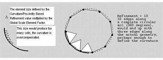
- Refinement
defines the number of edges that would fit along a radius of curvature if that radius were extended out to 360 degrees. This is generally used to avoid having too many elements along a given curve or surface, if the Min size limit is too small for that particular curve. Any positive integer can be entered for this option. See the example in Figure 237: Refinement.
- Ignore Wall Thickness
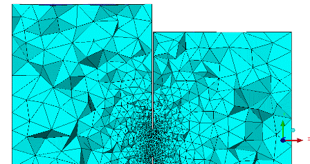
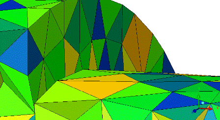
prevents the Curvature / Proximity Based sizing function from refining for closely spaced parallel surfaces, though it will still resolve other forms of proximity. The Elements in Gap function may cause the model to over-refine within or around thin walled sections of a model. In these cases, the refinement results in relatively uniform elements and high mesh density in those areas. This can dramatically increase the element count. Enabling the Ignore Wall Thickness option will result in a mesh that uses larger elements in the thin walled area. There will still be refinement near the edges of the thin wall, but it will not refine most of the area. These larger elements will not be uniform and are likely to have lower quality. These higher aspect ratio tetra elements are also more likely to result in holes or non-manifold vertices in the thin wall, which can be addressed using the Define Thin Cuts option for Octree Tetra meshing.
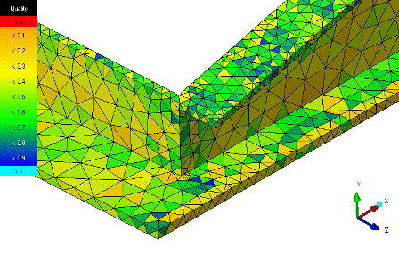
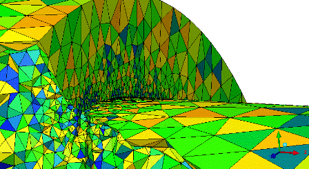
In the following examples, all refinement was controlled automatically by the Curvature / Proximity Based Refinement sizing function.
In the CFD example shown, there is a thin wall separating larger volumes. There is no need to refine the mesh for the wall thickness because meshing is not required within the wall. In this example, the quality is better when using Ignore Wall Thickness because of fewer size transitions.