


The Forte project used for System Coupling is in most aspects the same as the one used for a stand-alone CFD application, but the following settings are specific and important to System Coupling.
Enable System Coupling
You must enable System Coupling in the Forte project. To do so, load your Forte project, navigate to the Simulation Controls node on the Workflow tree, and enable the System Coupling item.
Select Coupling Interface(s)
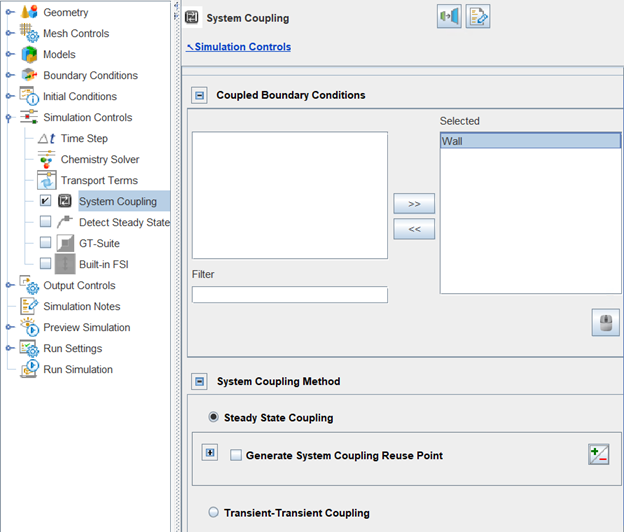
On the System Coupling panel, select the Coupled Boundary Condition(s) to participate in System Coupling. Figure 9.3: Selecting a coupled boundary condition on the System Coupling panel shows an example with the boundary condition named "Wall" selected. Here, the coupled boundary condition will be used as the coupling interface in System Coupling.
Note: At least one wall boundary must be selected as coupled boundary condition in order to use System Coupling. Any selected wall boundary condition must be associated with one and only one surface patch of the simulation domain.
Tip: When a boundary condition is selected for System Coupling, the output of solution variables is handled as an implicit wall sampling monitor probe. (To see how a wall sampling monitor probe works in general, refer to Probes for Time-Averaged and Spatially Resolved Data ). The output data provided at the coupling interface are spatially resolved solutions distributed on the selected wall boundary and time-averaged. As in a wall sampling probe, it is good practice to ensure sufficient surface mesh resolution on the boundary, which is used as the spatially resolved output resolution. Forte outputs data automatically, in the sense that you do not need to manually set up a wall sampling monitor probe in the User Interface for this purpose. There is a sampling frequency used for time averaging, which is implicitly set as the inquiry frequency on the Monitor Probes Editor panel (Monitor Probes Panel ). If there is no monitor probe present, the sampling frequency is implicitly set as the spatially averaged output frequency, specified in the Spatially Averaged Editor panel (Spatially Averaged and Spray Panel ). It is good practice to specify a sufficiently refined sampling frequency to produce accurate time-averaged output.
Select System Coupling Method
Once the desired coupling surfaces are selected, the System Coupling Method option allows selection between a Steady State (as in the example above) or a Transient system coupling simulation. Note that in both cases Forte will run in a transient mode, providing spatially resolved output variables on the coupled boundaries. The differences are:
In a steady-state coupled analysis, those variables will be time-averaged over the entire simulation time and transferred at the end of each coupling iteration to the other participant(s). In this case, Forte's simulation time is specified by the Simulation Limits on the Simulation Controls panel (see Simulation Limits Sub-panel). Forte's simulation time is repeated in each coupling iteration.
In a transient coupled analysis, the data will be averaged and transferred during each coupling time step. In this case, Forte's simulation time specified by the Simulation Limits on the Simulation Controls panel will be overwritten by the settings from System Coupling. Specifically, the end time and the coupling step size of System Coupling. Forte's simulation time marches as the system coupling step proceeds until its end time.
For the differences between a steady-state and a transient system coupling simulation, refer to Steady-State and Transient Coupled Analysis.
Select a Reuse Point (Optional, for Steady-State Coupled Analysis Only)
If the system coupling simulation is run as steady-state, the Generate System Coupling Reuse Point option can be activated, and a specific time/crank angle must be defined. The purpose of the Reuse Point is to reduce the simulation time of Forte in multiple coupling iterations. When activated, the first Forte run will be a complete run from initial to final specified time/crank angle and will generate a Forte restart file at the specified reuse time/crank angle point. Subsequent Forte runs for each coupling iteration will instead begin from the Reuse Point to the final time/crank angle, thus reducing the turn-around time per coupling iteration.
In a Conjugate Heat Transfer (CHT) analysis in engine simulations, the Reuse Point option is particularly beneficial. Forte's simulation time can be reduced when the portion between the start of the Forte simulation and the generated Reuse Point is not repeated in multiple coupling iterations. In an engine simulation, this portion can be the gas exchange phase of an engine cycle, which is insignificant in the CHT analysis.
Note: If specified as crank angle, the Reuse Point generation will be treated as cyclic and repeated on a 720-degree schedule (4-stroke) or 360-degree schedule (2-stroke). In multi-cylinder engine cases, the Reuse Point generation is applied with respect to each cylinder's local time frame. If multiple Reuse Points are generated during the first Forte run, Reuse Point(s) generated later will always override the previous one. Therefore, only the Reuse Point generated last will be taken as the restart point for the subsequent Forte runs.
Select Output Variables for System Coupling
The lower section of the System Coupling panel is dedicated to the selection of the Output Variables to be transferred on the coupling interface, and, if needed, initialized. For a CHT analysis, you may select the output variable on the coupling interface as Heat Rate, or alternatively, Heat Transfer Coefficient and Near Wall Temperature. Or, for a Fluid Structure Interaction (FSI) analysis, you may select the output variable as Force.
The Force applied by the fluid on the structure in FSI
analysis is calculated using the gauge pressure of the fluid in Forte. The
Reference Pressure input on the User Interface panel is used to
convert absolute pressure to gauge pressure:  .
.
In a CHT analysis, you may choose to initialize the data for Heat Rate, or alternatively, Heat Transfer Coefficient and Near Wall Temperature. For example, to initialize the Heat Rate on the boundary wall, click Add Boundaries to Initialize > Wall > Ok, and then add the desired value in Watts. Alternatively, if the same case has been previously run, click Import from previous Forte run, select the file wall_sampling_Wall_system_coupling.csv and the heat rate will be set as the average over the wall and over an entire iterative cycle. Additionally, at the bottom of the initialized data table, you can select the Default Heat Rate value to be applied to all the other boundaries not explicitly initialized in the table.
Tip: On a coupling interface of a CHT analysis, Forte can output Heat Rate, or alternatively, Heat Transfer Coefficient and Near Wall Temperature, and receives the wall temperature from System Coupling. The wall temperature is used to update the thermal boundary condition in the coupled iteration. When Fluent is the other Participant in the System Coupling run, Ansys recommends using Heat Rate as the output variable.
Finalize the Settings
Click Apply and save the project with File > Save. Your Forte project .ftsim file is now ready for use in System Coupling.
Note: Before attempting a System Coupling simulation, it is good practice to run Forte as a stand-alone project. This is a sanity check to detect if there is anything wrong or unexpected in the Forte project's setup. You may also know roughly how long it takes to complete a Forte simulation. To run the Forte project stand-alone, simply deactivate System Coupling under Simulation Controls. Please do not run a Forte-alone simulation with System Coupling activated, otherwise it might run into errors.