


While the Point Cloud Editor (Point Cloud Editor) is helpful in explicitly specifying the points’ coordinates, a more automated tool is helpful to quickly generate point cloud without much input. The Control Surface offers a convenient tool to automatically populate points on any clip plane within the simulation domain. This is useful in creating a Monitor Probe of the General Data Sampling type (see Probes for Time-Averaged and Spatially Resolved Data), which is designed to query spatially-resolved solutions inside the simulation domain.
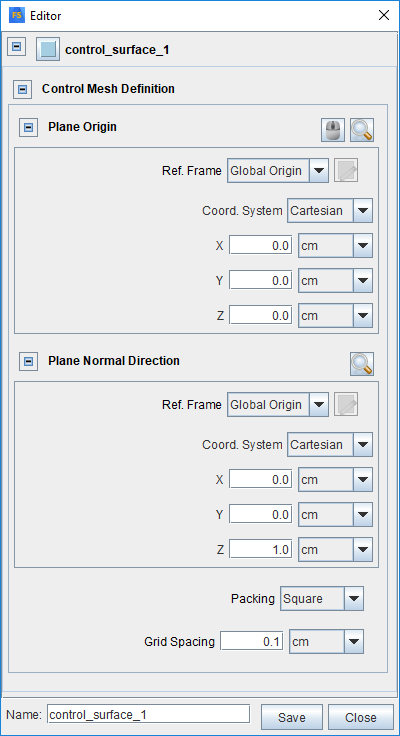
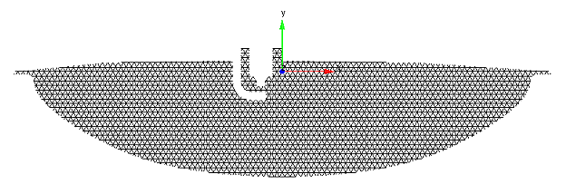
Use the Control Surface Editor (see Figure 2.19: Control Surface Editor) to define the control surface as well as its meshing. It is accessed from either a Monitor Probe’s Point Cloud Selector or from the Libraries menu. Use the Plane Origin and Plane Normal Direction to define the control surface (that is, the clip plane). Both can be specified by using a specified Reference Frame. In the example shown in Figure 2.19: Control Surface Editor, the plane’s Normal Direction is set to be the z-direction of the Global Origin Reference Frame. (For more information about how a Reference Frame is specified, refer to Reference Frames.) You can then select the Packing option to specify whether the meshing is square or triangular type, and indicate a grid spacing for the mesh. The resulting control surface and its meshing are displayed in the 3-D View window, as illustrated in Figure 2.20: Example of Control Surface and its meshing, as defined by the Control Surface Editor.
Once the control surface is defined, the auto-generated point cloud is assumed to be collocated on the mesh nodes. You may save the control surface and access it when setting up a Monitor Probe of General Data Sampling type.