


Turbomachinery geometries and simulations are governed by rotational periodicities. This periodicity can be taken advantage of to reduce the size of the modeled problem by using periodic interfaces. However, when the periodicity of the flow imposed does not match the periodicity of the geometry, normal periodic interfaces are not reliable. To be able to still benefit from using a reduced geometry, the Phase-lag boundary condition is introduced. This method usually allows you to limit the computational model to a single blade passage by applying a Phase-lag boundary condition on the boundaries where there would normally be periodic boundary conditions. The Phase-lag method can be used to apply periodic conditions that are phase-shifted in time to account for unequal pitches between adjacent blade rows (for transient-rotor-stator cases), to account for inequality between signal and domain pitches (for boundary disturbance cases), or to account for the inter-blade phase angle (for blade flutter cases).
The method aims to directly "impose" a phase shift between the S1 and S2 boundaries (as shown in Figure 14.13: Inlet Disturbance Configuration) for the primitive variables of the problem. A direct method of applying the phase shift boundary method was proposed by Erdos [41], but this method requires storage of the signal for a complete period on all the S1/S2 boundaries. The phase lag method makes use of temporal Fourier series decomposition (Equation 14–10) of the signal on both sides of the phase-lag interface to avoid storing the signal at each time step at the same boundaries. This method was initially introduced by L. He [61].
 | (14–10) |
In this method, the signal is decomposed into harmonics of the fundamental frequencies
 present in each passage as in Equation 14–10. For
example, in typical TRS problems or boundary disturbance problems, this fundamental
frequency is the inverse of the blade passing period
present in each passage as in Equation 14–10. For
example, in typical TRS problems or boundary disturbance problems, this fundamental
frequency is the inverse of the blade passing period  .
.
 | (14–11) |
The Phase-lag boundary approach converges very rapidly to a quasi-periodic state.
In Figure 14.13: Inlet Disturbance Configuration, an inlet disturbance configuration and how the phase shift/time shift is applied to the phase lag interfaces S1/S2 is illustrated.
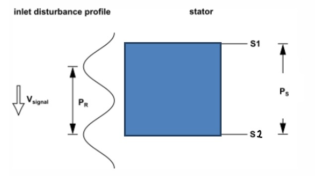
In that case, the phase shift between the two sides of the phase lag interface S1/S2 can be calculated as:
 | (14–12) |
and the equivalent time shift is:
 | (14–13) |
The signal on S1 is equal to the signal on S2 phase shifted by  . The signal on S2 is equal to the signal on S1 phase shifted by
 .
.
The phase lag method theoretically can be used in cases involving combinations of:
Rotational flow boundary disturbances
Blade flutter TWM (travelling wave method)
Transient-rotor-stator interactions
The Phase lag method is supported for inlet/outlet disturbances (which can include multiple simultaneous disturbances) and for blade flutter (TWM) cases.
For DBNS solutions, phase-lag is applied only to the following primitive variables:
static pressure, temperature, velocity components, turbulent kinetic energy, turbulent
dissipation rate ( ), and specific dissipation rate (
 ). For PBNS solutions, in addition to the above variables, phase-lag is
applied as well to the density, static enthalpy and all derivatives and reconstructed
gradients involved in the solution method chosen.
). For PBNS solutions, in addition to the above variables, phase-lag is
applied as well to the density, static enthalpy and all derivatives and reconstructed
gradients involved in the solution method chosen.
The current feature matrix is restricted to a subset of all the currently available models available in Fluent. The following models are officially supported:
K-epsilon, k-omega, and SST turbulence models.
Non-Equilibrium Condensation (Wet Steam) Model.
The basic procedure for setting up a transient turbomachinery simulation is outlined in Using the Turbomachinery Guided Workflow. The following are instructions for setting up a simulation with the Phase-lag method.
Available only for transient simulations.
Enable Turbo Models(/define/turbo-model/enable-turbo-model? y or from the ribbon).
 Domain →
Turbomachinery →
Domain →
Turbomachinery →
A phase-lag periodic interface in the pitch-wise direction is required on the outer periodic boundaries.
Ensure that no disturbance signal has a speed of zero relative to the component on which that signal acts.
The Turbomachine Description is required. This is automatically completed when using the Turbomachine Workflow (Using the Turbomachinery Guided Workflow) or you can manually complete the Turbomachine Description from the console (/define/turbo-model/create-turbomachine-description). For details, see Turbomachinery Description.
It is recommended to use either the
Frequency-BasedorPeriod-BasedTime Advancement Method with a sufficiently small time-step to run the phase-lag method. A recommended time-step size is to select the Frequency/Period to match the disturbance and then ensure a sufficiently high Time Steps per Period such as 40.Defining extra spectral settings for the Phase-lag method from the console:
/define/turbo-mode/phase-lag-extra-settingsProvides the option of changing defaults for spectral content creation for the Phase-lag method. In most cases, the default values are sufficient and need not be changed. The following options are available:
Fourier coefficients relaxation:
Under-relaxation constant to be applied to Fourier coefficient accumulation. Current default is 0.7 but a lower value could be used to improve robustness if required.
Number of initialization cycles:
Number of periods to run the simulation using the “periodic like BC” before starting Phase-lag. Permits delaying the onset of Phase-lag to have a better initial guesses for the Fourier coefficients for improved robustness at start-up.
Use the default number of Fourier harmonics for each fundamental frequency?
Uses the default number of harmonics for each fundamental base frequency. Alternatively, you must provide a list of harmonics for each fundamental frequency in the simulation. [default to y]
Enter the default number of Fourier harmonics of each fundamental frequency:
The number of harmonics to be applied as default to all base frequencies in the simulation [defaults to 10].
When solving a simulation that involves the Phase-lag method, the use of double precision is strongly recommended for accuracy and robustness.
The phase-lag interface can be created through two separate methods or the equivalent console commands.
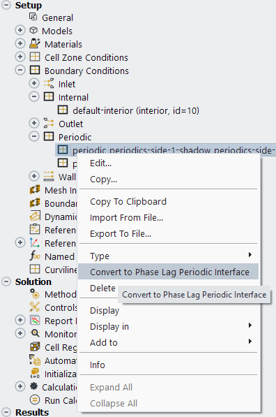
Right-click on a periodic boundary to convert to a phase-lag interface by selecting Convert to Phase Lag Periodic Interface in the menu.
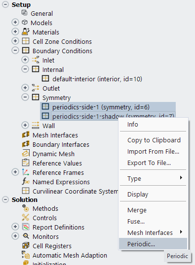
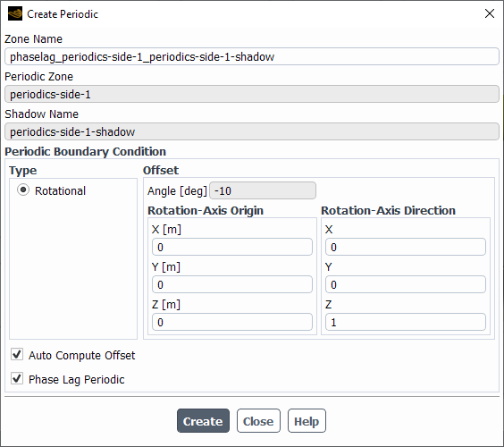
Multi-select the two boundaries that will make up the phase-lag interface, right-click, and select Periodic... from the menu as shown in Figure 14.15: Creating Phase Lag Periodic Interface from Boundaries. Then select Phase Lag Periodic at the bottom of the dialog box as shown in Figure 14.16: Create Periodic Dialog Box for a Phase-lag Interface.
From the console, there are equivalent commands for creating a phase-lag interface from a periodic interface or from boundaries.
For creating a phase-lag interface by converting a previously defined periodic interface:
/define/turbo-model/make-phaselag-from-periodicFor creating a phase-lag interface by specifying the two sides (boundaries) of the phase-lag Interface:
/define/turbo-model/make-phaselag-from-boundaries
In either case, Fluent prints the following message if the phase-lag interface was successfully created:
Successfully created a phase-lag interface
The setup of the phase-lag spectral content for both use-cases of blade flutter and inlet/outlet disturbance occurs automatically once the setup acquires enough information to fully specify the phase-lag parameters.
Once the phase-lag interface has been created, the phase-lag spectral description
needs to be set. For the inlet/outlet disturbance use case, it will be automatically
calculated if the profile contains the parameter
NumberSectors360, which represents the equivalent number of
blades in 360 degrees of the disturbance. There should be one parameter per disturbance
in the profile .csv file.
If there is more than one disturbance in the profile, then you need to append the
disturbance number to make the parameter unique. (for example,
NumberSectors360_2 for the second disturbance). From these
parameters the equivalent frequency and phase-lag angle will be calculated
automatically, and no further input is needed. If successful, Fluent prints the
following to the console.
Successfully created a phase-lag spectral description
Successfully initialized the phase-lag global spectral data structures
In cases where this parameter is not present in the profile
.csv file or in cases where the disturbance(s) are defined by
UDF, the phase-lag spectral description will need to be entered using the following text
command in the console:
/define/turbo-model/create-phaselag-spectral-content
It prompts for all the required input to specify the frequencies and phase-shift values associated with each disturbance of the simulation in each blade row. If you chose to not use the default number of Fourier harmonics for each fundamental frequency in the specifying spectral options step, you are prompted to list the desired harmonics for each frequency in the simulation. The frequencies can be specified as disturbances where it will be computed using the input number of sectors in the 360-degree machine and a reference frame or directly input as a real value in Hertz and the attached reference frame. See below for sample dialog from a session:
/define/turbo-model/create-phaselag-spectral-content
Add disturbances/frequencies manually? [no] yes
List of all rows: (row-1)
Enter the list of rows to add disturbances/frequencies: (1) [row-1]
Enter the number of disturbances/frequencies for row "row-1": [0] 2
For disturbance/frequency #1:
--> Enter type (1= blade passing disturbance, 2= real frequency in [Hz], 3= blade flutter disturbance): [-1] 1
--> Enter the reference frame associated with this disturbance/frequency Available: ("rotating" "global")
Reference Frame: [] rotating
--> Enter the number of sectors in 360 deg. associated with this disturbance: [0] 23
For disturbance/frequency #2:
--> Enter type (1= disturbance, 2=real frequency in [Hz]): [-1] 2
--> Enter the reference frame associated with this disturbance/frequency Available: ("rotating" "global")
Reference Frame: [] rotating
--> Enter the base frequency: (in [Hz]) [0] 7695
Again, the same message is reported to the console if successful.
For the blade flutter use-case, the spectral description is populated after the boundaries are specified for the dynamic mesh problem. When the vibrating blade(s) are selected, the attached mode shape is automatically queried for the frequency.The harmonic content is then populated and phase-lag angle calculated. To confirm this, Fluent prints the following to the console.
Successfully created a phase-lag spectral description
Successfully initialized the phase-lag global spectral data structures
To manually create the phase-lag spectral desription, you can use the following text command in the console:
/define/turbo-model/create-phaselag-spectral-content
The prompt list is similar but shorter than the inlet/outlet disturbance use-case because many of the spectral parameters can be automatically computed from the existing blade flutter setup.
/define/turbo-model/create-phaselag-spectral-content
Add disturbances/frequencies manually? [no] yes
List of all rows: (row-1)
Enter the list of rows to add disturbances/frequencies: (1) [row-1]
Enter the number of disturbances/frequencies for row "row-1": [0] 1
For disturbance/frequency #1:
--> Enter type (1= blade passing disturbance, 2= real frequency in [Hz], 3= blade flutter disturbance): [-1] 3
Again, the same message is reported to the console if successful.
The rest of the setup for a blade flutter case, can be found in Aerodynamic Damping (Blade Flutter Analysis).
There are additional commands for listing, appending, and deleting the phase-lag spectral content.
/define/turbo-model/list-phaselag-state
/define/turbo-model/append-phaselag-spectral-content
/define/turbo-model/delete-phaselag-spectral-content
For convenience, in addition to listing the phase-lag spectral content, the
list-phaselag-state command lists the turbomachine
description and graphics spectral content to give a better overview of the setup.
The suggested workflows to initialize Phase-lag simulations are as follows:
Steady state solution → switch to transient → modify case with appropriate phase-lag settings
This method usually results in the best convergence.
Read interpolated results from a steady-state solution into an existing transient phase-lag case.
Initialization from inlet → hybrid initialization → transient phase-lag setup
Important: After setting up a case with a phase-lag interface and then directly opening a
.dat file from the equivalent Steady-State solution, the
result is an error as the ghost-cells created for the phase-lag case will not have an
equivalent in the steady state solution. Following one of the above workflows is
recommended
Refer to General Fourier Coefficient Postprocessing for Turbomachinery Cases on how to enable and setup the simulation such that Fourier coefficients are available for postprocessing.