The Lithium-ion Battery model allows you to simulate the detailed physics governing the charging and discharging processes. The theoretical aspects of the Lithium-ion Battery model are presented in Lithium-ion Battery Model Theory in the Fluent Theory Guide.
Note that the Lithium-ion Battery model is designed to simulate detailed physics occurring on a very small electrode scale. If you are interested in the thermal aspect of the whole battery cell or a battery pack, consider a different modeling approach such as the dual potential MSMD battery model. See Using the MSMD-Based Battery Models for details.
The following sections contain details about the Lithium-ion Battery model. Only information for setting the Lithium-ion Battery model is provided here.
The electrode cell zone must be solid, and the electrolyte cell zone must be fluid.
The model can be used only for full electrode simulations; that is, the model must include a positive electrode zone, an electrolyte zone and a negative electrode zone. Half-cell models are currently not supported.
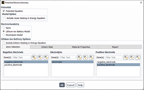
In the Potential/Electrochemistry dialog box, enable the Potential Equation (Potential group box) and the Lithium-ion Battery Model (Electrochemistry group box).
 Setup → Models →
Potential/Electrochemistry
Setup → Models →
Potential/Electrochemistry Edit...
The dialog box expands to reveal the parameters for the detailed lithium-ion battery model.
Note: Once the Lithium-ion Battery Model is enabled,Ansys Fluent automatically switches to the transient solver.
The inputs are grouped into the following tabs:
Zone Selection
Echem Rate
Material Properties
Report
You need to visit each tab and specify the lithium-ion battery model parameters for your analysis.
If you want to consider the electro-chemical reaction heat in the energy equation, select Include Echem Heating in Energy Equation.
In the Zone Selection tab (see Figure 30.2: The Potential/Electrochemistry Dialog Box - Echem Rate Tab), select appropriate zones from the Positive Electrode, Electrolyte Zone, and Negative Electrode selection lists.
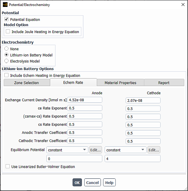
In the Echem Rate tab, define the Butler-Volmer rate parameters for the cathode and anode:
Exchange Current Density: is
 in Equation 18–9 in the Fluent Theory Guide.
ce Rate Exponent: is
 in Equation 18–9 in the Fluent Theory Guide.
(csmax-cs) Rate Exponent: is
 in Equation 18–9 in the Fluent Theory Guide.
cs Rate Exponent: is
 in Equation 18–9 in the Fluent Theory Guide.
Anodic Transfer Coefficient: is
 in Equation 18–9 in the Fluent Theory Guide.
Cathodic Transfer Coefficient: is
 in Equation 18–9 in the Fluent Theory Guide.
Equilibrium Potential: is
 in Equation 18–9 in the Fluent Theory Guide.
To customize Equilibrium Potential, you can use the
DEFINE_EC_KINETICS_PARAMETERuser-defined function (see the section onDEFINE_EC_KINETICS_PARAMETERin the Ansys Fluent Customization Manual for details).
If you want to use the linearized form of the Butler-Volmer equation (Equation 18–10 in the Fluent Theory Guide), select Use Linearized Butler-Volmer Equation.
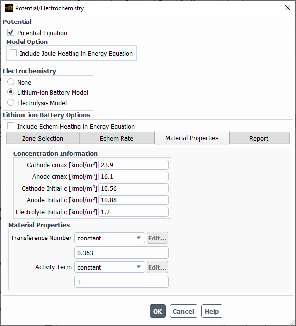
In the Material Properties tab, define the lithium concentration information and the material properties:
You can specify the following properties:
Concentration Information:
Cathode cmax: a maximum value of lithium concentration in the cathode (used in Equation 18–9 and Equation 18–10 in the Fluent Theory Guide).
Anode cmax: a maximum value of lithium concentration in the anode (used in Equation 18–9 and Equation 18–10 in the Fluent Theory Guide).
Cathode Initial c: lithium concentration in the cathode at the beginning of discharge (
 in Equation 18–4 in the Fluent Theory Guide).
Anode Initial c: lithium concentration in the anode side at the beginning of discharge (
in Equation 18–4 in the Fluent Theory Guide)Electrolyte Initial c: lithium-ion concentration in the electrolyte (
in Equation 18–4 in the Fluent Theory Guide)
Material Properties:
Transient Number is the lithium ion transference number
 in Equation 18–8 in the Fluent Theory Guide.
Activity Term is the term
 in Equation 18–8 in the Fluent Theory Guide.
In the Create/Edit Material dialog box, define materials for the negative electrode, positive electrode, and electrolyte. Make sure to specify proper values for Electrical Conductivity and Lithium Diffusivity for each material.
 Physics → Materials
→ Create/Edit...
Physics → Materials
→ Create/Edit...
In the Cell Zone Conditions task page, assign appropriate materials to different zones. The electrode cell zone must be solid, and the electrolyte cell zone must be fluid.
Physics → Zones →
Cell Zones
In the Potential tab of the Wall dialog boxes, define electric potential boundary conditions for the anode and cathode walls.
Physics → Zones →
Boundaries
Select one of the following options from the Potential Boundary Condition drop-down list:
Specified Flux and specify Current Density
Specified Value and specify Potential
For the anode, select Specified Value for Potential Boundary Condition. The default value of
0for Potential is usually adequate.For the cathode, when specifying Current Density, a negative value means current coming out of the domain, while a positive value means current flowing into the domain.
Note: There is no need to define any boundary condition for lithium.
In the Residual Monitors dialog box, set the convergence conditions for the potential and lithium equations. Usually you need to tighten the convergence criteria. For example, set
1.0e-10for the potential field, and1e-12for the lithium concentration field. Solution → Reports
→ Residuals...
(optional) If there is no flow field in the simulation, disable the Flow and Energy equations in the Equations dialog box (accessed from the Solution Controls task page).
Solution → Controls
→ Controls...
Initialize the flow field.
Note: The lithium and potential fields will be automatically initialized according to the information you provided in the Potential/Electrochemistry dialog box. No input is required from you for the two equations.
In the Solution Controls task page, adjust the under-relaxation factor for Faradaic Interface Current if necessary.
Solution → Controls
→ Controls...
Depending on the non-linearity of your problem, you can steer the solution by adjusting the value of the Faradaic Interface Current under-relaxation factor. If you are using a constant value for the Equilibrium Potential in the Butler-Volmer rate, you can use the default value of 0.01 or even a larger value. If you use a UDF to define equilibrium potential as a function of lithium concentration, then the coupling between potential and lithium concentration equation will be strong. Sometimes you may need to use a small value (as low as 0.001) in order to obtain a stable solution.
Once the lithium-ion battery model is enabled, Ansys Fluent automatically generates two report definitions:
li-ion-battery-socli-ion-battery-capacity
You can include these reports in report files or report plots (for example by right-clicking a report definition in the Outline View and selecting Include In > Report Plots > New...). In order for these report definitions to be computed correctly, make sure to correctly set lithium concentration at 0% and 100% SOC conditions (CLI at 0% SOC and CLI at 100% SOC in the Report tab).
Run the simulation.
If you use a low value for the Faradaic Interface Current under-relaxation factor, you may need to specify a large number for Max Iterations/Time Step in the Run Calculation task page. You can experiment with different numbers to find an appropriate value for your specific application. You can check the total current at the anode and cathode. The goal is that the two current values must be adequately balanced out during every time step in the simulation.
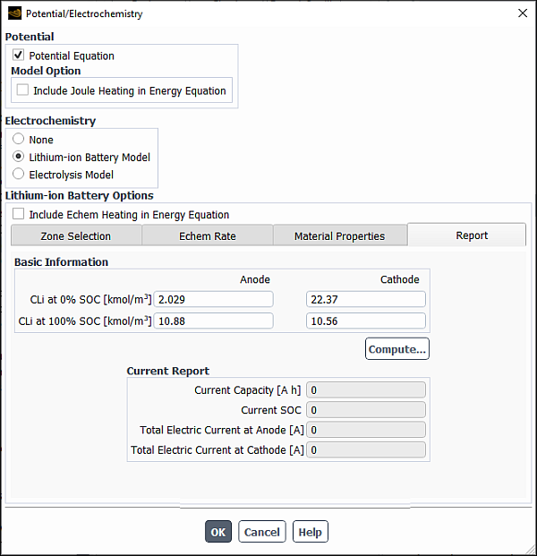
In the Report tab of the Potential/Electrochemistry dialog box, check the current balance at the SEIs in the negative and positive electrodes.
Specify the following values under Anode and Cathode:
CLI at 0% SOC: Lithium concentration at 0% SOC condition
CLI at 100% SOC: Lithium concentration at 100% SOC condition
Click .
In the Current Report group box, the solver reports battery’s current capacity, state of charge (SOC) and total current at anode and cathode SEIs.
Total current at anode and total current at cathode should be close enough to ensure good results. If they do not match, the solution has not fully converged. You may want to increase Max Iterations/Time Step and rerun your simulation.