


The electrolysis and H2 pump model can be used to simulate PEM electrolysis, and alkaline electrolysis. For more information about the theory behind the electrolysis and H2 pump model, see Electrolysis and H2 Pump Model in the Fluent Theory Guide.
The following sections contain details about the electrolysis and H2 pump model. Only information for setting the electrolysis and H2 pump model is provided here.
Since there is a number of different physical zones associated with the electrolysis device, the following regions must be present in the electrolysis model mesh:
Anode flow channel
Anode gas diffusion layer (porous layer)
Anode catalyst layer
Membrane layer
Cathode catalyst layer
Cathode gas diffusion layer (porous layer)
Cathode flow channel
In addition, the following zones must be identified, if present in the electrolysis model mesh:
Anode current collector (solid)
Cathode current collector (solid)
The following describes an overview of the procedure required in order to use the electrolysis and H2 pump model in Ansys Fluent.
Start Ansys Fluent.
Read the case or mesh file.
Scale the mesh, if necessary.
Enable and set up electrolysis and H2 pump model as described in Setting up the Electrolysis and H2 Pump Model.
Define material properties.
In the Create/Edit Materials dialog box, under Properties, you must specify Electrical Conductivity and Electrolyte Conductivity for the collector, porous, catalyst, and electrolyte materials defined in your simulation. The material electrical and electrolyte conductivities can be specify as constant, a function of temperature in forms of piecewise-linear, piecewise-polynomial or polynomial, an expression, or as a user-defined function using the
DEFINE_PROPERTYmacro.Set the operating conditions.
Set the boundary conditions for the flow.
Note: Ansys Fluent automatically sets boundary conditions for the electric potential field. They are suitable for most cases and should not be modified.
Start the calculations.
Save the case and data files.
Process your results.
Note: The Potential/Electrochemistry dialog box greatly simplifies the input of parameters and boundary conditions, but it does not replace the boundary conditions interface. Therefore, it is a good practice to start the setup with the Potential/Electrochemistry dialog box and do the finishing steps for boundary conditions afterwards.
In the Potential/Electrochemistry dialog box enable Potential Equation (in the Potential group box), and Electrolysis and H2 Pump Model (in the Electrochemistry group box).
 Setup → Models →
Potential/Electrochemistry
Setup → Models →
Potential/Electrochemistry  Edit...
Once the electrolysis and h2 pump model has been enabled, Ansys Fluent automatically enables the mixture multiphase phase and specie transport models.
Note: The electrolysis and H2 pump model uses the mixture multiphase model to consider multiphase phenomena. It cannot be used with VOF or Eulerian multiphase model.
The dialog box expands to reveal the parameters for the detailed electrolysis and H2 pump model. The model settings are organized into the following tabs:
- Model
contains the general model settings to define problems that involve the electrolysis and H2 pump model.
- Parameters
is where you specify parameters for solving the model equations.
- Anode
allows you to select the appropriate anode zones and specify their properties.
- Electrolyte
allows you to select the appropriate electrolyte/membrane zones and specify their properties.
- Cathode
allows you to select the cathode zones and specify their properties.
- Electrical Tabs
is where you can select anode and cathode tabs.
- Customization
is where you can customize electrolysis model parameters by hooking your user-defined functions (UDFs).
- Advanced
is where you can specify contact resistivity at the interface between cell zones.
If you want to consider the electro-chemical reaction heat in the energy equation, select Include Echem Heating in Energy Equation (Potential group box).
Identify the relevant zones for the current collectors, flow channels, gas diffusion layers (porous layers), catalyst layers, and the electrolyte (membrane) and specify all relevant parameters.
Refer to the following sections for more information:
- 30.3.3.1. Specifying Model Options (Model Tab)
- 30.3.3.2. Specifying Model Parameters (Parameters Tab)
- 30.3.3.3. Specifying Anode Properties (Anode Tab)
- 30.3.3.4. Specifying Electrolyte/Membrane Properties (Electrolyte Tab)
- 30.3.3.5. Specifying Cathode Properties (Cathode Tab)
- 30.3.3.6. Setting the External Electrical Tabs (Electrical Tabs Tab)
- 30.3.3.7. (Customization Tab)
- 30.3.3.8. Setting Advanced Options (Advanced Tab)
The Model tab of the Potential/Electrochemistry dialog box allows you to enable or disable various general options and specify relevant settings when solving an electrolysis problem.
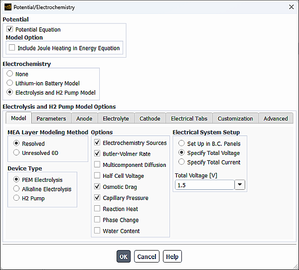
- MEA Layer and H2 Pump Method
In the MEA Layer and H2 Pump Method group box, you can select the modeling approach for the membrane electrode assemblies (MEA) zones (the catalyst layers and the membrane). The following options are available:
Resolved
Refer to Resolved Modeling Approach in the Fluent Theory Guide for details about this approach.
Unresolved 0D
Refer to Unresolved 0D Modeling Approach in the Fluent Theory Guide for details about this approach.
- Device Type
In the Device Type group box, you can select from the following electrolysis processes you want to model:
PEM Electrolysis
Alkaline Electrolysis
H2 Pump
The main difference between the two is that different electrochemistry is applied in the calculation.
- Options
You can use the following options:
- Electrochemistry Sources
allows the electrolysis and H2 pump model to take electrochemistry effects into account. If you are only interested in the basic potential field throughout the electrolysis and H2 pump model, you can disable the Electrochemistry Sources option to suppress most effects of the electrolysis and H2 pump model. You may also disable the effect of these sources to obtain an initial fluid flow and then enable it and continue your simulation.
- Butler-Volmer Rate
(default) is used to compute the transfer currents inside the catalyst layers. If this option is disabled, the Tafel approximation is used (Equation 20–7 and Equation 20–8).
- Multicomponent Diffusion
is used to compute the gas species mass diffusivity using the full multicomponent diffusion method (Full Multicomponent Diffusion in the Fluent Theory Guide).
- Half Cell Voltage
enables the calculations of the anode and cathode half-cell potentials using the Nernst equations (Equation 20–13 and Equation 20–14 in the Fluent Theory Guide). If this option is disabled, the constant open-circuit voltage is assumed.
- Osmotic Drag
when enabled, includes the osmotic drag effects into calculation.
- Capillary Pressure
when enabled, includes the capillary pressure effects in the calculation. Capillary pressure facilitates the transport of the gaseous species produced in the catalyst layer through the porous layer into the flow channel.
- Reaction Heat
when enabled, takes into account the heat generated by the electrolysis reactions.
- Phase Change
when enabled, takes into account the phase change between liquid water and water vapor.
- Water Content
when enabled, solves the transport equation of water content using Equation 18–20 and Equation 18–21 in the Fluent Theory Guide.
If you want to account for the effect of the membrane hydration level on the electrolyte conductivity, you can define electrolyte conductivity of the electrolyte material using the DEFINE_PROPERTY user-defined function. This option is only available for the resolved approach.
- Electrical System Setup
In the Electrical System Setup group box, you can select one of the following methods to set up the electrical potential boundary conditions at external wall tabs:
- Set Up in B.C. Panels
when enabled, Ansys Fluent uses your electrical potential boundary conditions that you specified in the relevant boundary condition dialog boxes.
- Specify Total Voltage
allows you to specify Total Voltage, which is the cell or stack voltage (V). You have the option to specify the Total Voltage as a constant (default) or expression. See Creating and Using Expressions for more information about the expression specification method.
The Potential Boundary Condition and Electrolyte Potential Boundary Condition specified in the boundary condition dialog boxes (Potential tab) for anode and cathode are ignored. Ansys Fluent automatically sets the potential to zero at the cathode tabs and applies a fixed value of Total Voltage at the anode tabs.
- Specify Total Current
allows you to specify Total Current, which is the total current (Amps) generated by the cell or stack. You have the option to specify the Total Current as a constant (default) or expression. See Creating and Using Expressions for more information about the expression specification method.
The Potential Boundary Condition and Electrolyte Potential Boundary Condition specified in the boundary condition dialog boxes (Potential tab) for anode and cathode are ignored. Ansys Fluent automatically sets the potential to zero at the cathode tabs and applies a constant flux (current density) at the anode tabs.
In the Parameters tab of the Potential/Electrochemistry dialog box, you can set the electrochemistry parameters and model parameters on the anode and cathode sides.
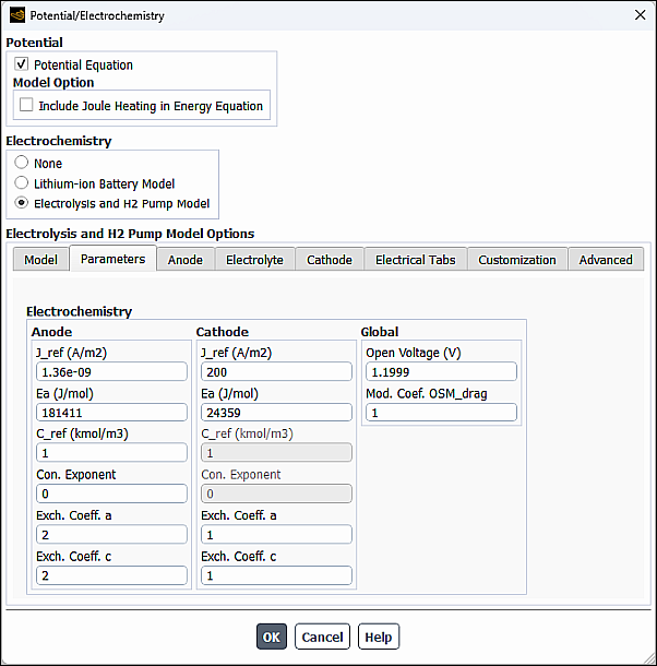
In the Electrochemistry group box, you can specify the following parameters or leave the default values. on the anode and cathode sides:
- J_ref
is the reference exchange current density
 and
and  in Equation 20–9 and Equation 20–10 in the Fluent Theory Guide.
- Ea
is the permeation activation energy
 in Equation 20–9 and Equation 20–10 in the Fluent Theory Guide.
- C_ref
is the reference concentration
 and
and  in Equation 20–5 and Equation 20–6 in the Fluent Theory Guide in units of 1
kg-mol/m3. Note that for the PEM
Electrolysis and H2 Pump device types, this parameter is
available only for anode, while for the Alkaline Electrolysis device
type, it is available only for cathode.
in Equation 20–5 and Equation 20–6 in the Fluent Theory Guide in units of 1
kg-mol/m3. Note that for the PEM
Electrolysis and H2 Pump device types, this parameter is
available only for anode, while for the Alkaline Electrolysis device
type, it is available only for cathode.- Con. Exponent
is the concentration dependence
 and
and  in Equation 20–5 and Equation 20–6 in the Fluent Theory Guide. Note that for the
PEM Electrolysis and H2 Pump device types, this
parameter is available only for anode, while for the Alkaline
Electrolysis device type, it is available only for cathode.
in Equation 20–5 and Equation 20–6 in the Fluent Theory Guide. Note that for the
PEM Electrolysis and H2 Pump device types, this
parameter is available only for anode, while for the Alkaline
Electrolysis device type, it is available only for cathode.- Exch. Coeff. a , Exch. Coeff. c
are the transfer coefficients
 and
and  in Equation 20–5 and Equation 20–6 in the Fluent Theory Guide.
- Std. State E0
are the reversible potentials
 and
and  in Equation 20–13 and Equation 20–14 in the Fluent Theory Guide. This field appears only when
Half Cell Potentials option is selected in the
Model tab.
in Equation 20–13 and Equation 20–14 in the Fluent Theory Guide. This field appears only when
Half Cell Potentials option is selected in the
Model tab.- Entropy
is the reaction entropy
 and
and  in Equation 20–13 and Equation 20–14 in the Fluent Theory Guide.
In addition, you can specify the following Global parameters:
- Open Voltage
is the constant value of open-circuit voltage assigned to anode half-cell potential
 in Equation 20–11 in the Fluent Theory Guide. When Open Voltage is specified, the
cathode half-cell potential
in Equation 20–11 in the Fluent Theory Guide. When Open Voltage is specified, the
cathode half-cell potential  is set to zero. This parameter appears only when Half Cell
Voltage is disabled in the Model tab.
is set to zero. This parameter appears only when Half Cell
Voltage is disabled in the Model tab.- Standard Temperature
is the reference standard state temperature
 used for half-cell potentials computations in the Nernst equations (Equation 20–13 and Equation 20–14 in the Fluent Theory Guide). This parameter appears only when Half Cell
Voltage is enabled in the Model tab.
used for half-cell potentials computations in the Nernst equations (Equation 20–13 and Equation 20–14 in the Fluent Theory Guide). This parameter appears only when Half Cell
Voltage is enabled in the Model tab.- Standard Pressure
is the reference standard state pressure
 , which is used for half-cell potentials computations in the Nernst
equations (Equation 20–13 and Equation 20–14 in the Fluent Theory Guide). This parameter appears only when Half Cell
Voltage is enabled in the Model tab.
, which is used for half-cell potentials computations in the Nernst
equations (Equation 20–13 and Equation 20–14 in the Fluent Theory Guide). This parameter appears only when Half Cell
Voltage is enabled in the Model tab.- Vaporization Rate
is the evaporation rate (
 in Equation 18–22 in the Fluent Theory Guide). This
parameter appears only when Phase Change is enabled in the
Model tab.
in Equation 18–22 in the Fluent Theory Guide). This
parameter appears only when Phase Change is enabled in the
Model tab.- Condensation Rate
is the condensation rate (
 in Equation 18–22 in the Fluent Theory Guide). This
parameter appears only when Phase Change is enabled in the
Model tab.
in Equation 18–22 in the Fluent Theory Guide). This
parameter appears only when Phase Change is enabled in the
Model tab.- Mod. Coef. OSM_drag
is the constant
 in Equation 18–22 in the Fluent Theory Guide. The
default value is 1.0 for PEM and alkaline electrolysis, and 0.001 for the H2 pump. This
parameter appears only when Osmotic Drag is enabled in the
Model tab.
in Equation 18–22 in the Fluent Theory Guide. The
default value is 1.0 for PEM and alkaline electrolysis, and 0.001 for the H2 pump. This
parameter appears only when Osmotic Drag is enabled in the
Model tab.
In the Anode tab of the Potential/Electrochemistry dialog box, you can specify zones and properties of the following zones for the anode portion of the electrolysis and H2 pump model:
Current collector
Flow channel
Porous layer
Catalyst layer (resolved approach only)
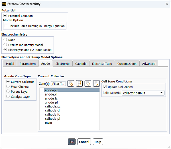
In the Anode Zone Type group box, select Current Collector.
From the Zone(s) multiple-selection list, select a corresponding zone(s).
From the Solid Material drop-down list (Cell Zone Conditions group box), select the appropriate material from the default Ansys Fluent materials (collector-default, porous-default, catalyst-default, and electrolyte-default). The default values of electrical conductivity and electrolyte conductivity for the default Ansys Fluent materials are shown in the table below.
Material Property collector-default porous-default catalyst-default electrolyte-default Electrical conductivity (S/m) 1e6 1e4 1e4 1e-16 Electrolyte conductivity (S/m) 1e-16 1e-16 2.3677 2.3677 You can use the Create/Edit Materials dialog box to customize solid material properties.
The cell zone conditions you specify are applied to all selected zones in the Zone(s) list. If you want to set the cell zone conditions for each zone individually (using the Cell Zone Conditions task page), you should disable the Update Cell Zones option.
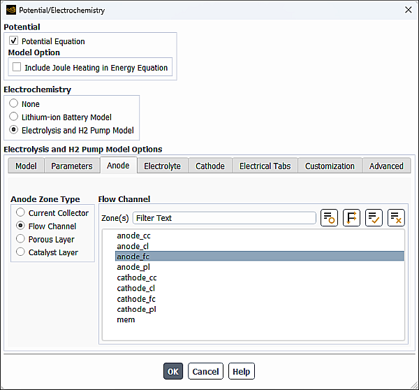
In the Anode Zone Type group box, select Flow Channel.
From the Zone(s) multiple-selection list, select an appropriate zone(s).

In the Anode Zone Type group box, select Porous Electrode.
From the Zone(s) selection list, select a corresponding zone(s).
Select the solid material as described in Specifying Current Collector Properties for the Anode.
Specify values for the following cell zone parameters:
- Porosity
- Absolute Permeability
is the inverse of viscous resistance
 in Equation 7–4.
- Capillary Pressure
allows you to choose a capillary pressure definition method. You can choose leverett-function or your own user-defined function. See
DEFINE_CAPILLARY_PRESSUREin the Fluent Customization Manual for more information.If you choose leverett-function, you need to define the following parameters:
- Contact Angle
is
 in Equation 20–35.
- Leverett Func. Coeff_a
is the Leverett function coefficient
 in Equation 20–37 (default
= 1.417).
in Equation 20–37 (default
= 1.417).- Leverett Func. Coeff_b
is the Leverett function coefficient
 in Equation 20–37 (default
= 2.12).
in Equation 20–37 (default
= 2.12).- Leverett Func. Coeff_c
is the Leverett function coefficient
 in Equation 20–37 (default
= 1.263).
in Equation 20–37 (default
= 1.263).

Figure 30.10: The Anode Tab of the Potential/Electrochemistry Dialog Box with the Catalyst Layer Selected - Resolved Approach
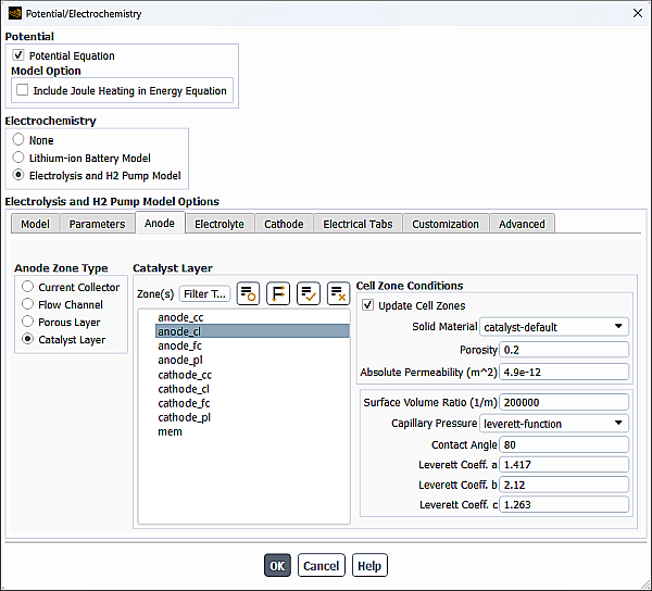
Resolved Approach
Settings for the Catalyst Layer are similar to those for the Porous Layer described in Specifying Porous Layer Properties for the Anode.
For the catalyst layer, in addition to the cell zone parameters defined in Specifying Porous Layer Properties for the Anode, you can also specify the following parameter:
- Surface Volume Ratio
is the specific active surface area (
 in Equation 20–5 for the anode and
 in Equation 20–6 in the Fluent Theory Guide for the cathode).
Unresolved Approach
You can specify the following parameters:
- Surface Volume Ratio
is the specific active surface area of the anode and cathode, respectively (
 Equation 18–28 in the Fluent Theory Guide and
  in Equation 18–29 in the Fluent Theory Guide).
- Layer Thickness
is the thickness of the anode catalyst layer (
 Equation 18–28 in the Fluent Theory Guide for the anode catalyst
layer, and
Equation 18–28 in the Fluent Theory Guide for the anode catalyst
layer, and  in Equation 18–29 in the Fluent Theory Guide for
the cathode catalyst layer).
in Equation 18–29 in the Fluent Theory Guide for
the cathode catalyst layer).- Catalyst Electrical Conductivity
is the electrical conductivity of the catalyst layer (
 and
and  in Equation 18–27 in the Fluent Theory Guide for
the anode and cathode, respectively).
in Equation 18–27 in the Fluent Theory Guide for
the anode and cathode, respectively).
In the Electrolyte tab of the Potential/Electrochemistry dialog box, you can specify settings of the electrolyte/membrane portion of the electrolysis device. Settings are different for the resolved and unresolved MEA layer methods. Further details are provided in the following sections:
When Resolved is selected as the MEA Layer and H2 Pump Method (Model tab), you can specify zones and properties of the electrolyte/membrane portion of the electrolysis device in the Electrolyte tab of the Potential/Electrochemistry dialog box.
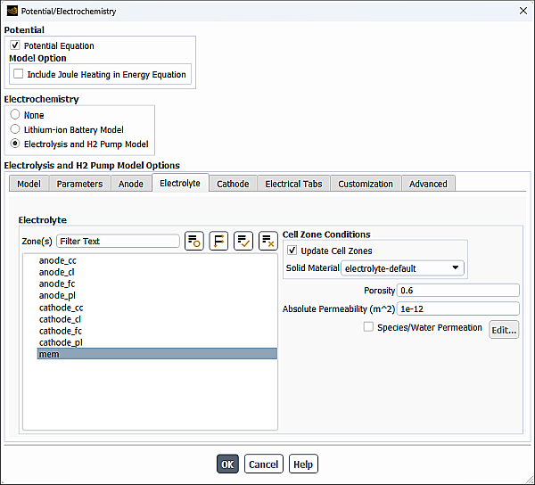
From the Zone(s) selection list, select a corresponding zone(s).
Select the solid material as described in Specifying Current Collector Properties for the Anode.
Specify the following parameters for the selected cell zone:
- Porosity
- Absolute Permeability
is the inverse of viscous resistance
 in Equation 7–4.
If you want to account for species or liquid water crossing the membrane from the higher to the lower pressure side, enable Species/Water Permeation and click Edit....
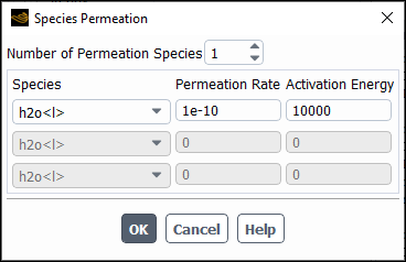
In the Species Permeation dialog box that opens, enter the Number of Permeation Species. Use the arrows to change the value, or type in the value and press Enter.
Select each species you want to consider in the Species drop-down list and specify the following parameters:
- Permeation Rate
is the permeation rate constant
 in Equation 18–24 in the Fluent Theory Guide.
- Activation Energy
is the permeation activation energy
in Equation 18–24 in the Fluent Theory Guide.
When Unresolved 0D is selected as the MEA Layer and H2 Pump Method (Model tab), you can specify electrolyte interfaces and MEA parameters of the electrolyte/membrane portion of the electrolysis device in the Electrolyte tab of the Potential/Electrochemistry dialog box.
Figure 30.13: The Electrolyte Tab of the Potential/Electrochemistry Dialog Box - Unresolved MEA Layer
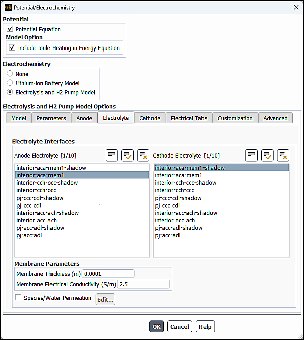
In the Anode Electrolyte and Cathode Electrolyte selection lists, select pairs of wall/wall shadow. The solver uses the selected pairs to determine where the electrochemistry sources are added.
In the MAE Parameters group box, specify the following parameters:
- Membrane Thickness
is the conductivity of the membrane (
 in Equation 18–27 in the Fluent Theory Guide).
- Membrane Electrical Conductivity
is the conductivity of the membrane (
 in Equation 18–27 in the Fluent Theory Guide).
If you want to account for species or liquid water crossing the membrane from the higher to the lower pressure side, enable Species/Water Permeation and specify the species permeation as described in Resolved MEA Layer Method.
The procedures for specifying the properties for the current collector, flow channel, porous layer, and catalyst layer on the cathode side are similar to those on the anode side. For specific steps, refer to Specifying Anode Properties (Anode Tab) and substitute “cathode” for “anode” where appropriate.
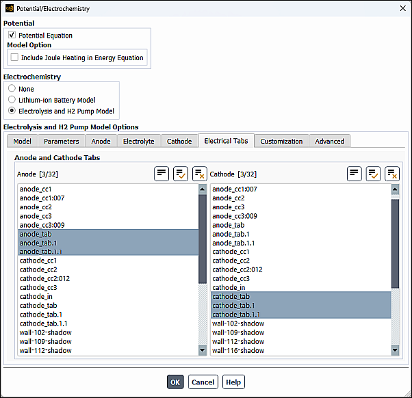
In the Electrical Tabs tab of the Potential/Electrochemistry dialog box, you can specify Anode and Cathode Tabs. The anode and cathode tabs are the external wall surfaces where electrical potential boundary conditions are applied using the method specified in the Electrical System Setup group box (Model tab).
In the Customization tab of the
Potential/Electrochemistry dialog box, you can use the
DEFINE_ELECTROLYSIS_ECHEM_RATE and
DEFINE_ELECTROLYSIS_RELATIVE_PERMEABILITY user-defined functions to
customize the transfer currents and relative permeability. See DEFINE_ELECTROLYSIS_ECHEM_RATE and
DEFINE_ELECTROLYSIS_RELATIVE_PERMEABILITY
in the Fluent Customization Manual for more information.
In the Advanced tab of the Potential/Electrochemistry dialog box, you can specify Contact Resistivity at the interface between cell zones.
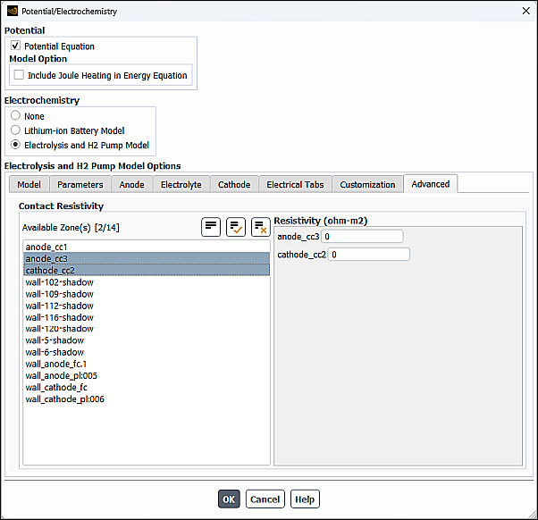
From the Available Zone(s) selection list, select any number of corresponding interfaces. These are face zones over which a jump in electrical potential is caused by imperfect conduction.
Specify a value for the Resistivity for each specified zone.
Note that at porous jump and wall/wall-shadow interfaces, the contact resistivity is applied at each face. Therefore, you need to specify the resistivity only at one of the interface walls, otherwise the actual resistance will be doubled at the interface.
It may be useful to disable Include Joule Heating in Energy Equation (Potential group box) and Electrochemistry Sources (Model tab) in the Potential/Electrochemistry dialog box for the first few (approximately 10-20) iterations after initialization. This allows the two potentials to adjust from their initial values to more physical values, avoiding the possibility of extreme electrochemical reactions and electric currents that would in turn adversely impact the solution.