


In the Wall dialog box, under the Wall Film tab, you can set boundary, initial, and source term conditions for liquid films on specified wall boundaries. When you select the Eulerian Film Wall option, Fluent solver designates the wall as a film wall. Wall film equations are only solved on designated film walls.
Note that the wall film edges connected to symmetry or periodic flow boundaries will also be treated as symmetry and periodic for the film flow. Film wall edges that are not connected to other designated film walls, symmetry boundaries, or periodic flow boundaries will be treated as film flow outlets where the wall film liquid exits the designated film walls.
The inputs are grouped into the following tabs:
Boundary Type
Source Terms
Phase Change
Surface Contact
DPM Interaction
VOF Interaction
For additional information, see the following sections:
In the Boundary Type tab, you can select the film condition type and specify film conditions.
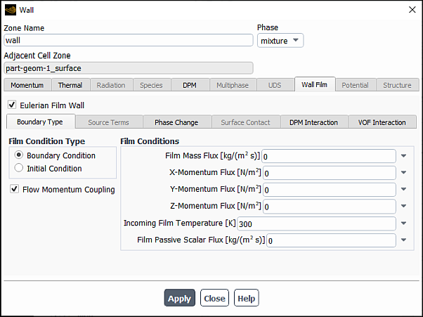
The following types of film conditions exist in Ansys Fluent:
Boundary Condition: Is where film mass, momentum, energy and scalar quantities are introduced to the wall film solution domain.
You can enter values for the following quantities:
Film Mass Flux
X-Momentum Flux, Y-Momentum Flux, and Z-Momentum Flux
Incoming Film Temperature
Film Passive Scalar Flux
For moving wall simulations, you can specify the film momentum flux relative to the wall on which liquid film is defined by selecting Relative Film Momentum Flux. Note that this option is only available when Moving Wall is selected in the Wall dialog box and/or Frame Motion is selected in the Fluid dialog box.
the film momentum flux or initial velocity inputs will be relative to the wall on which liquid film is defined.
Initial Condition: Is the initial state of wall film.
You can set values for the following quantities:
Film Height
X-Velocity, Y-Velocity, and Z-Velocity components
Film Temperature
Film Passive Scalar
For moving wall simulations, you can specify the initial velocity relative to the wall on which liquid film is defined by selecting Relative Initial Film Velocity. Note that this option is only available when Moving Wall is selected in the Wall dialog box and/or Frame Motion is selected in the Fluid dialog box.
For both boundary and initial conditions, if you select the Flow Momentum Coupling option, the liquid film and the gas flow shares the same velocity at the interface of the liquid-gas interface using a two-way coupling. If you clear this option, the coupling between the liquid film and the gas flow occurs only one-way, namely, while the gas flow impacts the film flow, the film flow does not impact the bulk of the gas flow.
The Sources Terms tab is available only with Initial Condition.
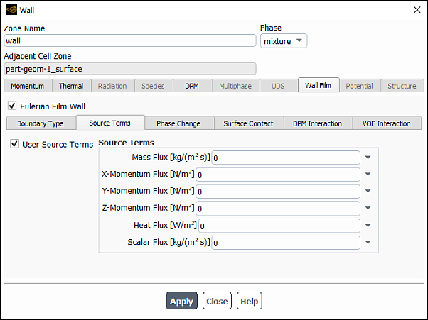
If you select the User Source Terms option, you can also specify additional source terms to the film continuity, momentum, energy, and passive scalar equations by setting values for the following quantities:
Mass Flux
X-Momentum Flux, Y-Momentum Flux, and Z-Momentum Flux
Heat Flux
Scalar Flux
When the Phase Change option is selected in the Eulerian Wall Film dialog box, you can enable the Film Phase Change for the selected film wall, and then select the Phase Change Model and specify the model parameters in the Phase Change tab.
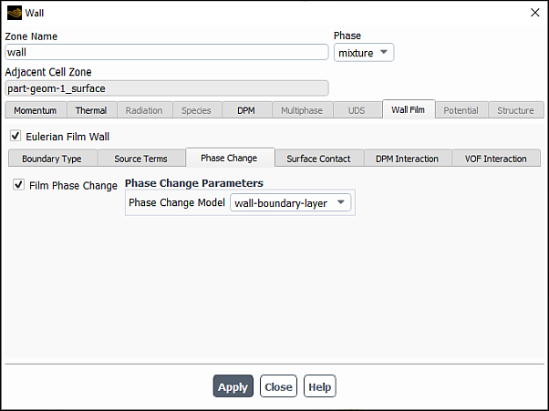
The following phase change models are available:
diffusion-balance
For the diffusion-balance model, you can specify Condensation Constant and Vaporization Constant.
wall-boundary-layer
No user input is required for this model.
user-defined
For the user-defined model, you can specify Condensation Rate and Vaporization Rate as constants, parameters, or profile user-defined functions (UDFs). Note that condensation and vaporization rates must be specified as positive values in kg/s. For more information on profile UDFs, the separate Fluent Customization Manual.
For more information on the phase change models see Coupling of Wall Film with Mixture Species Transport in the Fluent Theory Guide.
For cases with the initial condition, if you select the Surface Tension option in the Eulerian Wall Film dialog box, then you can enable the partial wetting model for the selected film wall by selecting the Film Contact Angle option in the Surface Contact tab.
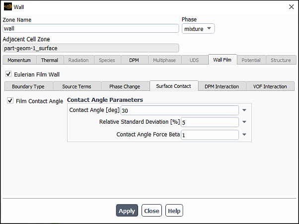
You can then specify the following parameters in the Contact Angle Parameters group box:
Mean Contact Angle (
 in Partial Wetting Effect in the Fluent Theory Guide)
The input range for the mean Contact Angle is 0 to 180 degrees. You can also use a user-defined profile UDF. The UDF must return a contact angle value within the above range in radian. For more information on profile UDFs, the separate Fluent Customization Manual.
Relative Standard Deviation (
 in Partial Wetting Effect in the Fluent Theory Guide)
The input for the Relative Standard Deviation should be in the range of 0 to 50%.
Contact Angle Force Beta (
 in Equation 17–29 in the Fluent Theory Guide)
The input range for Contact Angle Force Beta is 0 to 10.
For more information on modeling the film partial wetting effect, see Partial Wetting Effect in the Fluent Theory Guide.
When the DPM Coupling option is selected in the Eulerian Wall Film dialog box, you can select a particle-wall impingement model and specify relevant model parameters in the DPM Interaction tab of the Wall dialog box.
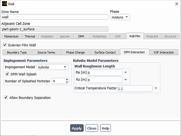
The following impingement models are available in Ansys Fluent:
stanton-rutland (see The Stanton-Rutland Model in the Fluent Theory Guide for details)
kuhnke (see The Kuhnke Model in the Fluent Theory Guide for details)
For the Kuhnke model, you must specify the following model parameters:
Ra: The wall mean roughness that is used to compute
 in Equation 12–249 in the Fluent Theory Guide
Rz: The average surface roughness that is used to compute splashed particle reflection angle distribution Equation 12–261 in the Fluent Theory Guide.
Critical Temperature Factor: The dimensionless variable that is used to determine the impingement regime transition temperature in Equation 12–239 in the Fluent Theory Guide.
stochastic kuhnke (see The Stochastic Kuhnke Model in the Fluent Theory Guide for details)
For the stochastic Kuhnke model, specify the following parameters in the Kuhnke Model Parameters group box:
Rz under the Wall Roughness Length: This parameter will be used to interpolate the constant
 from Parameter A as a Function of Wall Roughness in the Fluent Theory Guide, which will be subsequently used in Equation 12–267 in the Fluent Theory Guide to calculate critical
Weber number for splashing on a dry wall.
from Parameter A as a Function of Wall Roughness in the Fluent Theory Guide, which will be subsequently used in Equation 12–267 in the Fluent Theory Guide to calculate critical
Weber number for splashing on a dry wall.Upper Deposition Limit Offset: Is
 in Equation 12–264 in the Fluent Theory Guide.
Deposition Delta T: Is
 in Equation 12–265 in the Fluent Theory Guide.
Laplace Number Constant: Is
 in Equation 12–266 in the Fluent Theory Guide.
Partial Evaporation Ratio: Is the mass fraction of the impinging liquid spray that vaporizes immediately upon impact when the droplet is in the evaporative splash regime.
Note: You can also add an impingement effect via UDFs as described in Hooking DEFINE_IMPINGEMENT UDFs, Hooking DEFINE_FILM_REGIME UDFs, and Hooking DEFINE_SPLASHING_DISTRIBUTION UDFs in the Fluent Customization Manual. Note that UDFs
settings will override those for the impingement/splashing model selected for the Eulerian
wall film boundary condition.
In addition, when Particle Splashing is selected in the Eulerian Wall Film dialog box, you can select DPM Wall Splash and specify Number of Splashed Particles.
When the Edge Separation option is enabled in the Eulerian Wall Film dialog box, you can select the Allow Boundary Separation option to allow a separation at disconnected internal film wall boundaries.
When the VOF Coupling option is selected in the Eulerian Wall Film dialog box (Phase Interaction tab), you can enable and set the Film/VOF Transition & Criteria and specify the Relaxation Factor in the VOF Interaction tab.
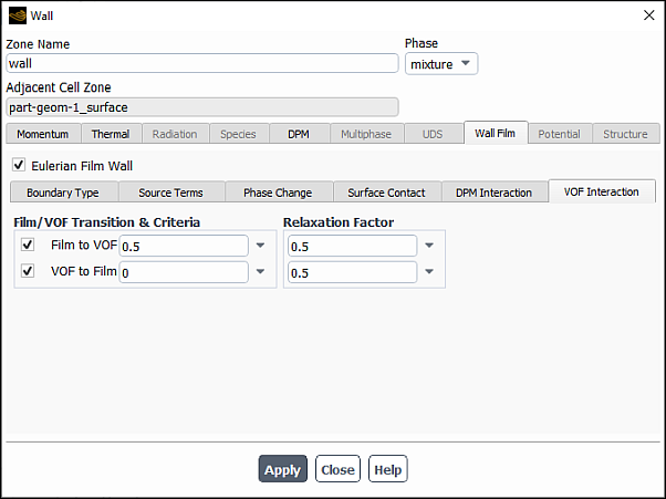
The Film to VOF and VOF to Film transition criteria are fraction values between 0 and 1 of either Volume Fraction or Height Fraction as specified in the Eulerian Wall Film dialog box (Phase Interaction tab, Transition Base group box). The Film to VOF transition criterion must be larger than the VOF to Film transition criterion. A weighted film thickness threshold is computed based on the specified transition criterion value and used to determine the onset of the transition.
The Film-to-VOF transition occurs when either the film thickness is larger than the Film to VOF threshold, or the film thickness exceeds Maximum Thickness specified in the Eulerian Wall Film dialog box (Solution Method and Control tab).
The VOF-to-Film transition occurs when the equivalent film thickness (computed from the relevant fraction values) is smaller than the VOF to Film threshold.
The thickness threshold values for the Film to VOF and VOF to Film transitions are displayed in the Fluent console once these settings are applied and during the model initialization.
The relaxation factors are values in the range of 0 to 1 (default: 0.5). They are used to control the release of transferred source terms and improve the stability of the solution process. In general, higher transition criteria tend to make the solution unstable and, therefore, may require smaller relaxation factors.