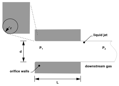
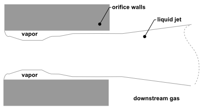
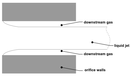
The plain-orifice is the most common type of atomizer and the most simply made. However there is nothing simple about the physics of the internal nozzle flow and the external atomization. In the plain-orifice atomizer model in Ansys Fluent, the liquid is accelerated through a nozzle, forms a liquid jet and then breaks up to form droplets. This apparently simple process is dauntingly complex. The plain orifice may operate in three different regimes: single-phase, cavitating and flipped [618]. The transition between regimes is abrupt, producing dramatically different sprays. The internal regime determines the velocity at the orifice exit, as well as the initial droplet size and the angle of droplet dispersion. Diagrams of each case are shown in Figure 12.17: Single-Phase Nozzle Flow (Liquid Completely Fills the Orifice), Figure 12.18: Cavitating Nozzle Flow (Vapor Pockets Form Just After the Inlet Corners), and Figure 12.19: Flipped Nozzle Flow (Downstream Gas Surrounds the Liquid Jet Inside the Nozzle).
To accurately predict the spray characteristics, the plain-orifice model in Ansys Fluent must identify the correct state of the internal nozzle flow because the nozzle state has a tremendous effect on the external spray. Unfortunately, there is no established theory for determining the nozzle state. One must rely on empirical models obtained from experimental data. Ansys Fluent uses several dimensionless parameters to determine the internal flow regime for the plain-orifice atomizer model. These parameters and the decision-making process are summarized below.
A list of the parameters that control internal nozzle flow is given in Table 12.7: List of Governing Parameters for Internal Nozzle Flow. These parameters may be combined to form nondimensional
characteristic lengths such as r/d and L/d, as well as
nondimensional groups like the Reynolds number based on hydraulic "head"
and the cavitation parameter K [482].
Table 12.7: List of Governing Parameters for Internal Nozzle Flow
| nozzle diameter |
|
| nozzle length |
|
| radius of curvature of the inlet corner |
|
| upstream pressure |
|
| downstream pressure |
|
| viscosity |
|
| liquid density |
|
| vapor pressure |
|
(12–353) |
(12–354) |
The liquid flow often contracts in the nozzle, as can be seen
in Figure 12.18: Cavitating Nozzle Flow (Vapor Pockets Form Just After the Inlet
Corners) and Figure 12.19: Flipped Nozzle Flow (Downstream Gas Surrounds the Liquid Jet
Inside the Nozzle). Nurick [482] found it helpful to use a coefficient of contraction
() to represent the reduction
in the cross-sectional area of the liquid jet. The coefficient of
contraction is defined as the area of the stream of contracting liquid
over the total cross-sectional area of the nozzle. Ansys Fluent uses Nurick’s
fit for the coefficient of contraction:
(12–355) |
Here, is a theoretical
constant equal to 0.611, which comes from potential flow analysis
of flipped nozzles.
Another important parameter for describing the performance of
nozzles is the coefficient of discharge (). The coefficient
of discharge is the ratio of the mass flow rate through the nozzle
to the theoretical maximum mass flow rate:
(12–356) |
where is the effective mass flow
rate of the nozzle, defined by
(12–357) |
Here, is the mass flow rate specified in the
user interface, and
is the difference between
the azimuthal stop angle and the azimuthal start angle
(12–358) |
as input by you (see Point Properties for Plain-Orifice Atomizer Injections in the User’s
Guide). Note that the mass flow rate that you input should be for
the appropriate start and stop angles, in other words the correct
mass flow rate for the sector being modeled. Note also that for of
, the
effective mass flow rate is identical to the mass flow rate in the
interface.
The cavitation number ( in Equation 12–354) is an essential parameter for
predicting the inception of cavitation. The inception of cavitation is assumed to occur at a
value given by the following empirical relationship:
(12–359) |
Similarly, a critical value of where flip occurs is given by
(12–360) |
If is greater than 0.05, then flip is deemed impossible
and
is set to 1.0.
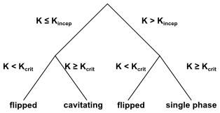
The cavitation number, , is compared to the values of
and
to identify the nozzle state. The decision
tree is shown in Figure 12.20: Decision Tree for the State of the Cavitating Nozzle. Depending
on the state of the nozzle, a unique closure is chosen for the above
equations.
For a single-phase nozzle () [370], the coefficient of discharge is given by
(12–361) |
where is the ultimate
discharge coefficient, and is defined as
(12–362) |
For a cavitating nozzle () [482] the
coefficient of discharge is determined from
(12–363) |
For a flipped nozzle () [482],
(12–364) |
All of the nozzle flow equations are solved iteratively, along with the appropriate relationship for coefficient of discharge as given by the nozzle state. The nozzle state may change as the upstream or downstream pressures change. Once the nozzle state is determined, the exit velocity is calculated, and appropriate correlations for spray angle and initial droplet size distribution are determined.
For a single-phase nozzle, the estimate of exit velocity () comes from the conservation
of mass and the assumption of a uniform exit velocity:
(12–365) |
For the cavitating nozzle, Schmidt and Corradini [581] have shown that the uniform exit velocity is not accurate. Instead, they derived an expression for a higher velocity over a reduced area:
(12–366) |
This analytical relation is used for cavitating nozzles in Ansys Fluent. For the case of flipped nozzles, the exit velocity is found from the conservation of mass and the value of the reduced flow area:
(12–367) |
The correlation for the spray angle () comes from the work of
Ranz [541]:
(12–368) |
The spray angle for both single-phase and cavitating nozzles
depends on the ratio of the gas and liquid densities and also the
parameter . For flipped nozzles, the spray
angle has a constant value.
The parameter , which you must specify, is
thought to be a constant for a given nozzle geometry. The larger the
value, the narrower the spray. Reitz [548] suggests
the following correlation for
:
(12–369) |
The spray angle is sensitive to the internal flow regime of
the nozzle. Hence, you may want to choose smaller values of for cavitating
nozzles than for single-phase nozzles. Typical values range from 4.0
to 6.0. The spray angle for flipped nozzles is a small, arbitrary
value that represents the lack of any turbulence or initial disturbance
from the nozzle.
One of the basic characteristics of an injection is the distribution
of drop size. For an atomizer, the droplet diameter distribution is
closely related to the nozzle state. Ansys Fluent’s spray models
use a two-parameter Rosin-Rammler distribution, characterized by the
most probable droplet size and a spread parameter. The most probable
droplet size, is obtained
in Ansys Fluent from the Sauter mean diameter,
[351]. For more information about the Rosin-Rammler
size distribution, see Using the Rosin-Rammler Diameter Distribution Method in the User's Guide.
For single-phase nozzle flows, the correlation of Wu et al. [719] is used to calculate and
relate the initial drop size to the estimated turbulence quantities
of the liquid jet:
(12–370) |
where ,
is the radial integral length scale at
the jet exit based upon fully-developed turbulent pipe flow, and We
is the Weber number, defined as
(12–371) |
Here, is the droplet surface tension. For a more
detailed discussion of droplet surface tension and the Weber number,
see Secondary Breakup Model Theory. For more information
about mean particle diameters, see Summary Reporting of Current Particles in the User’s
Guide.
For cavitating nozzles, Ansys Fluent uses a slight modification
of Equation 12–370. The initial jet diameter
used in Wu’s correlation, , is calculated from the effective area of the cavitating
orifice exit, and therefore represents the effective diameter of the
exiting liquid jet,
.
For an explanation of effective area of cavitating nozzles, see Schmidt
and Corradini [581].
The length scale for a cavitating nozzle is , where
(12–372) |
For the case of the flipped nozzle, the initial droplet diameter is set to the diameter of the liquid jet:
(12–373) |
where is defined
as the most probable diameter.
The second parameter required to specify the droplet size distribution
is the spread parameter, . The values for the spread parameter are chosen
from past modeling experience and from a review of experimental observations.
Table 12.8: Values of Spread Parameter for Different Nozzle States lists the values of s for the
three nozzle states. The larger the value of the spread parameter,
the narrower the droplet size distribution.
Table 12.8: Values of Spread Parameter for Different Nozzle States
| State | Spread Parameter |
|---|---|
| single phase | 3.5 |
| cavitating | 1.5 |
| flipped |
|
Since the correlations of Wu et al. provide the Sauter mean
diameter, , these are
converted to the most probable diameter,
.
Lefebvre [351] gives the most general relationship
between the Sauter mean diameter and most probable diameter for a
Rosin-Rammler distribution. The simplified version for
=3.5 is as follows:
(12–374) |
At this point, the droplet size, velocity, and spray angle have been determined and the initialization of the injections is complete.


