


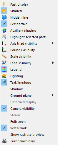
The View menu allows the user to change overall rendering area view features, including various visibility toggles, overall object display look and extended visual capabilities such as stereo, full screen and detached display modes. Some of the menu options are the same as the Tools Icon Bar global toggle icons as indicated below:
|
Fast display |
Toggles the Fast display mode. By default, EnSight displays all of the lines and elements for each part every time the rendering window redraws. If you have very large models (or if you have slow graphics hardware), each redraw can take significant time. As a result, interactive transformations become jerky and lag behind the motion of the mouse. Ironically, the slower the graphics performance, the harder it is to perform precise interactive transformations. To avoid this problem, you can tell EnSight to show a lesser detailed part representation, for example, a bounding box surrounding each Part, or the Part as a point cloud. You can select to show the detail representation all the time, or only while you are performing transformations. This obviously displays much less information, but may be sufficient if you want to rotate a very large model. |
|
|
A lesser detail display is also useful when experimenting with keyframe-animation rates. Using lesser detail, the display rate can be adjusted to approximate the video rate, thus you can see how your scene will transform on the video tape. |
||
|
The default setting is off, indicating that all lines and elements of all visible parts will be redrawn. When on, the redraw will show only the part's Fast Display Representation (by default a box). The fast display representation is only used while transformations are being performed. The fast display representation will be continuously displayed if the Static Fast Display option is turned on in: Edit → Preferences → Performance → Static fast display. |
||
|
Shaded Toggle |
Toggles the Global Shaded mode for parts on and off. EnSight by default displays parts in line mode. Shaded mode displays parts in a more realistic manner by making hidden surfaces invisible while shading visible surfaces according to specified lighting parameters. Parts in Shaded mode require more time to redraw than when in line mode, so you may wish to first set up the Graphics Window as you want it, then turn on Shaded to see the final result. Shaded can be toggled on/off for individual parts by using the Shaded Toggle icon in the Tools Icon Bar. (see 5.1.1, Parts Quick Action Icons and Set Drawing Mode) |
|
|
Hidden line |
Toggles the global Hidden line display for all parts on/off. This simplifies a line drawing display by making hidden lines - lines behind surfaces - invisible while continuing to display other lines. Hidden Line can be combined with Shaded to display both surfaces and the edges of the visible surface elements. Hidden Line can be toggled on/off for individual parts by using the Hidden Line Toggle icon in the Part Quick Action Icon Bar. To have lines hidden behind surfaces, you must have surfaces (2D elements). If the representation of the in-front parts consists of 1D elements, the display is the same whether or not you have Hidden Lines mode toggled on (see 5.1.1, Parts Quick Action Icons and Set Drawing Mode). The Hidden line overlay dialog will be displayed if the Shaded option is currently on and you then turn the Hidden Line option on. The section Troubleshooting Auxiliary Clipping contains solution to common hidden line display issues. |
|
|
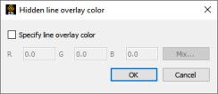
Hidden line overlay dialog |
This dialog is used to specify a color for the displayed lines. If this color is not different from the surface color, the lines will not be visually distinguishable from the surfaces. The default is the part-color of each part, which may be appropriate if the surfaces are colored by a color palette instead of their part-color.
|
|
| Specify line overlay color |
Toggle-on if you want to specify an overlay color. If off, the overlay line color will be the same as the part color. |
|
| R, G, B |
The red, green, and blue components of the hidden line overlay. These fields will not be accessible unless the Specify line overlay color option is on. |
|
| Mix... |
Click to interactively specify the constant color used for the hidden line overlay using the system Color selector dialog (see Parts Quick Action Icons). |
|
| OK |
Click to accept the hidden line overlay color options. |
|
|
Perspective |
Toggles the view within each of the viewports within the Graphics Window between a perspective view (the default) and an orthographic projection. Perspective is what provides the sense of depth when viewing a three dimensional scene on a two dimensional surface. Objects that are far away look smaller and parallel lines seem to meet at infinity. Orthographic projection removes the sense of depth in a scene. Lines that are parallel will never meet and objects of the same size all appear the same no matter how far away they are from you. Orthographic projection mode often helps when you are positioning the Cursor, Line, and Plane tools using multiple viewports. This is the Global toggle. Each viewport also has a Perspective Toggle (see Set Global Viewing Parameters). |
|
|
Auxiliary clipping |
Toggles the Auxiliary clipping feature on/off. (Default is Off). Like a Z-Clip plane, Auxiliary clipping cuts-away a portion of the model. When Auxiliary clipping is On, Parts (or portions of Parts) located on the back (negative-Z) side of the Plane Tool are removed. Parts whose Clip attribute you have toggled off (in the General Attributes section of the Feature Panel or with the Auxiliary clipping toggle icon in the Part Quick Action Icon Bar) remain unaffected. Auxiliary clipping is interactive - the view updates in real time as you move the Plane Tool around (see 4.6, Tools Menu Functions and Use the Plane Tool). |
|
|
Unlike a Z-Clip plane, Auxiliary clipping applies only to the parts you specify, and the plane can be located anywhere with any orientation though it is always infinite in extent (see 6.4, Z-Clip and Set Z Clipping). Auxiliary clipping is helpful, for example, with internal flow problems since you can peel off the outside parts and look inside. This capability is also often useful in animation. The position of the Plane Tool and the status of Auxiliary clipping is the same for all displayed viewports. Do not confuse Auxiliary clipping with a 2D-Clip plane, which is a created part whose geometry lies in a plane cutting through its parent parts or with the Part operation of cutting a part.(see 5.1.3, Clip Parts, Create Clip Planes, and Cut Parts). The section Troubleshooting Auxiliary Clipping contains solution to common auxiliary clipping issues. (See also Set Auxiliary Clipping) |
||
|
Highlight selected part(s)... |
Highlight the selected parts in the graphics window. This often aids in the identification of parts. |
|
|
Axis triad visibility |
A sub-menu which allows you to toggle on/off the visibility of the Global axis triad, the axis triads for all Frames, and the model axis triad. |
|
|
Frame |
Toggles (default is On) the display of all coordinate Frame axis triads. The visibility of individual coordinate Frame axes can be selectively turned on/off by clicking on the Frame's axis triad and then clicking on the Frame Axis Triad Visibility Toggle in the Frame Quick Action Icon Bar. |
|
|
Global |
Toggles (default is Off) the display of the global coordinate frame axis. The global coordinate frame axis triad represents the Look-At Point. |
|
|
Model |
Toggles the display of the model axis triad in the lower left of the screen. This triad is not at the origin of frame 0, but is aligned with it (see Tools Icon Bar). |
|
|
Bounds visibility |
Toggles (default is Off) the extents box for all parts. |
|
|
Scale visibility |
Toggle on/off the visibility of a scale showing dimensionality in the viewport. The scale will be shown as a horizontal ruler at the bottom of the viewport. Only viewports that are in orthographic mode or 2D mode will show the ruler. There are currently no per-viewport controls for the scale nor attributes that can be changed by you. |
|
|
Label visibility |
A sub-menu which allows you to toggle the visibility of labels for Elements or Nodes. |
|
|
Element labeling |
Toggles (default is Off) the global visibility of labels for elements in all parts. Element labels will only be displayed if they are available in the dataset. Visibility of element labels for individual parts can be controlled via the Node/Element labeling icon in the Quick Action Icon Bar. |
|
|
Node labeling |
Toggles (default is off) the global visibility of labels for nodes in all parts. Node labels will only be displayed if they are available in the dataset. Visibility of node labels for individual parts can be controlled via the Node/Element labeling icon in the Quick Action Icon Bar. |
|
|
Labeling attributes... |
Opens the Node/Element labeling dialog from which you can control the labeling visibility, color, and filtering for selected parts. This same dialog can also be reached from the Node/Element labeling icon in the Quick Action Icon Bar. |
|
|
Legend |
Toggles (default is on) the global visibility of all legends. The visibility of individual legends can be controlled by using the Legend tab in the Annotation Feature Panel (see Variable Summary & Palette) and Create Color Legends. |
|
This dialog is used to specify the location, type, intensity, and color of up to eight light sources. By default, a single directional light source exists, located at the user, pointing in the direction of the view. This light source is always light source 1, and can not have it's type modified. For more information, see Light Source Editor . |
||
|
Text/Line/Logo |
Toggles global visibility for text strings and lines which have been created and logos which have been imported. The visibility of individual Text strings, Lines, or Logos can be controlled by selecting the item in the annotation list and selecting the context sensitive Hide or Show menu items. It can also be toggled from the associated Annotation Feature Panel (Create Lines, Create Text Annotation and Load Custom Logos). |
|
|
Shadow |
Toggles the visibility of shadows. For more information, see Create Shadow Rendering. |
|
|
Ground plane |
Toggles the visibility of the ground plane and opens a dialog with ground plane settings. For more information, see Ground Plane Editor. |
|
|
Detached display |
This menu item is disabled unless using a detached display. If you have a detached display then it is automatically enabled and toggled on, and this menu item allows toggling on/off this detached display. |
|
|
Camera Visibility |
Toggles the global visibility for cameras. The visibility of individual cameras can be controlled by selecting the camera in the Transformation editor (Camera) dialog. |
|
|
Stereo |
Toggles the stereo rendering mode for the 3D rendering window. Note: Stereo display capability must be supported by graphics hardware and the connected monitor. |
|
|
Fullscreen |
Toggles the fullscreen mode of the 3D rendering window. |
|
|
Watermark |
Toggles the display of the Ansys logo on the upper right corner of the 3D rendering window. |
|
|
Show Raytrace Preview |
Toggles the display of the raytracing preview. The preview is displayed as a logo image. You can also toggle its visibility via the Annotations tab in the main graphical user interface. |
|
|
Turbomachinery |
This menu will launch the Turbomachinery tool and the Instances by default. For more information on the usage of this tool, see Turbomachinery. |
|
The following topics are included in this section:
| Problem | Probable Causes | Solutions |
|---|---|---|
|
Main View shows line drawing after turning on the Shaded toggle |
Shaded is toggled off for individual parts |
Toggle Shaded on for individual parts with the Shaded icon in the Part Quick Action Icon Bar or in the Feature Panel. |
|
There are no surfaces to shade - all parts have only lines. |
If parts are currently in Feature Angle representation, change the representation. If model only has lines, one cannot display shaded images. | |
|
The Main View window shows nothing other than the Plane Tool after Clipping is toggled-on. |
The element visibility attributes has been toggled off for the part(s). |
Toggle the element visibility on for individual parts in the Feature Panel. |
| Problem | Probable Causes | Solutions |
|---|---|---|
|
The Plane Tool does not appear to clip anything |
The Auxiliary Clipping toggle is off for all parts. |
Turn the Auxiliary Clipping toggle on for individual parts in the Feature Panel (Model) dialog General Attributes section. |
|
The Plane Tool is not intersecting the model |
Change the position of the Plane Tool. | |
|
The Main View window shows nothing other than the Plane Tool after Clipping is toggled-on. |
All of the part(s) is(are) on the back side of the Plane Tool and is(are) thus clipped |
Change the position of the Plane Tool. |