


EnSight displays the scene in a three-dimensional, rectangular workspace that has finite boundaries on all sides. Even if you rotate the model, you are always looking into the workspace from the front side. The top-to-bottom and side-to-side boundaries of the workspace are analogous to looking out a real window - the window frame limits your view. In addition, since the memory of your computer is finite, your workspace also has limits in the front-and-back direction.
The front boundary is the Front Clipping Plane (or the Near Plane ) and the rear boundary is the Back Clipping Plane (or the Far Plane). Only the portion of the scene between these two planes is visible - the rest of the model (if any) is clipped and therefore invisible. By convention, the front-to-back direction of the workspace is the Z direction. Hence, the front and back clipping planes are together called the Z-Clip Planes.
Note: The Z-direction in the workspace is always in-and-out of the screen and is completely independent of the Z-direction of the model Frame (Frame 0).
The position of the Z-Clip planes is specified in terms of their distance from the Look From Point in the distance units implied by the model-geometry data. By default, the planes automatically move as the model moves.
Initially, EnSight positions the Z-Clip Planes based on the dimensions of the model parts read to the Client, with some extra space for you to perform transformations. You can reposition the planes when doing so becomes necessary or desirable.
Each viewport has its own independently adjustable set of Z-Clip Planes.
You can use Z-Clip planes to deliberately clip-away portions of the model you are not interested in, or which are getting in the way of what is of interest. For example, you can clip-away both a front-portion and a back-portion of a model to reduce the number of node and element labels displayed. Z-Clip Planes and EnSight uses your workstation's graphics hardware to perform all graphics manipulations, including the display of solid surfaces.
The appearance of a solid model is created by not displaying hidden surfaces - surfaces hidden behind nearer surfaces. The algorithm used by the graphics hardware to do this task - Z-buffering - is a simple algorithm which compares Z-values to calculate which surfaces are closest to you and thus visible. Z-buffering is normally performed in integer arithmetic, and on most graphics systems is confined to 24 bits of resolution. Hence, the coordinates in Z must be mapped into this 24-bit space. To achieve the maximum resolution possible in the 24 bits available, the graphics hardware maps the Z-distance between the Front and Back Clipping Planes into the 24 bits available. Hence, the larger the distance between the Z-Clip Planes, the lower the Z resolution, which can affect image quality for solid images. If you see problems with your solid images, move the front and back clipping planes in as close as possible.
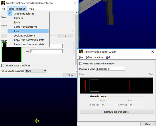
The Transformation Editor (Z-Clip) is used to adjust the distances of the Front and Back Clipping Planes from the Look-From Point.
- Float Z Clip Planes With Transform
When on, will automatically adjust the front and back Z-Clip planes away from the model.
- Minimum Z Value
Minimum distance the Front Clipping Plane is allowed to float to from the Look From Point (model coordinates). Used only if Float Z Clip Planes with Transform toggle is on.
- Z-Clip Area Display
Displays position of Z-Clip planes relative to model-part Z-range (shown as a rectangle) and allows interactive positioning (by clicking and dragging) of the Z-Clip planes. If lines are inside model rectangle, that part of model is clipped from the display. Values update in data fields as you move sliders. Active viewports of the Main View update automatically as you move sliders.
- Plane Distance
- Front
Distance of the Front Clipping Plane from Look From Point in model coordinates. Precisely specify by typing in desired distance and pressing Enter. Not used if the Float Z Clip Planes With Transform toggle is on.
- Back
Distance of the Back Clipping Plane from the Look From Point in model coordinates. Precisely specify by typing in desired distance and pressing Enter. Not used if the Float Z Clip Planes With Transform toggle is on.
- Redraw Z-Clip Area Above
The Plane Position Display does not automatically update if you perform transformations in the active viewport. Click this button to update the Plane Position Display.
| Problem | Probable Causes | Solutions |
|---|---|---|
| Main View is empty | No parts located between Front and Back Z-Clip Planes. | Toggle off the Float Z-Clip toggle and adjust Z-Clip plane locations |
| Model degenerates to irregular polygons or the front Z-Clip line is locked in the model extent box | You have moved the front Z-Clip plane too close to (or on) the Look From Point. | Move the front Z-Clip plane away from the Look From Point. |