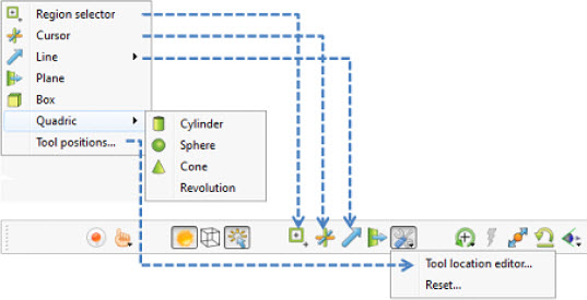
The Region selector, Cursor, Line, Plane, Box, and Quadric (cylinder, sphere, cone, and revolution) Tools in EnSight are used for a variety of tasks, such as: positioning of clipping planes and lines, query operations, particle trace emitters, etc. Collectively these tools are referred to as Positioning Tools. Clicking Tools in the Main Menu opens a pull-down menu which provides access to these tools. Several of the tools have quick action icons below the Main Graphics Window, as shown in the figure below, to toggle their visibility.
|
Region selector Toggle |
Makes the Selection Tool (region selector) visible/invisible in the Graphics Window. The Selection Tool appears as a white rectangle with four symbols at the upper left of the tool (left to right: element blanking, zoom, select parts showing, select parts all layers). It may be repositioned interactively in the Graphics Window by selecting and dragging it or by selecting any corner and rubber banding the corner. Note: A dotted rectangle, which stays at the same aspect ratio of the screen, will indicate the actual selection area as it is manipulated. Alternatively, you can reposition it precisely by specifying X and Y min/max coordinates in the Transformation Editor dialog (described in Tool Positions... → Region Tool below). Tools → Region selector or Tools Icon Bar → Selection tool. See Use the Selection Tool |
|
|
Cursor |
Makes the Cursor Tool visible/invisible in the Graphics Window. The Cursor Tool appears as a three-dimensional cross colored red, green, and blue. The red axis of the cross corresponds to the X axis direction for the currently selected Frame, while green corresponds to the Y axis and blue corresponds to the Z axis. The Cursor Tool is initially located at the Look-At point and may be repositioned interactively in the Graphics Window by left-clicking and dragging it or right-clicking it and choosing Edit on the pulldown which opens the Transformation Editor. If you have a specific location you want to click on and have the cursor moved there, then select Pick Cursor Location from the Pick Pull-down icon menu in the Tools Icon Bar. |
|
|
Line |
Opens a pull-down menu with options for toggling the visibility of the Line Tool as well as options for restricting where the Line Tool is drawn. These options are described below. The Line Tool appears as a high contrast (black on light background, white on black background) line with a dotted-line axis system at the center point and an arrowhead on its 2nd endpoint. The Line Tool is initially centered about the Look-At point and sized so that it fills approximately 10% of the default view. There are a number of ways to manipulate the tools either interactively or via the transformation dialog. You can change its length and orientation interactively in the Graphics Window by selecting one of its end points. You can rotate the line tool by clicking and dragging on the center axes. You can reposition it interactively in the Graphics Window by selecting its center and dragging it or by selecting Pick Line Location from the Pick Pulldown icon menu in the Tools Icon Bar. Alternatively, you can reposition it precisely by rotating, translating, or specifying coordinates in the Transformation Editor dialog by right-clicking on the line tool and selecting Edit. If you have a precise location that you want to locate the line tool you can select Pick Line Tool Location from the Pick Pull-down icon menu in the Tools Icon Bar. See Use the Line Tool. |
|
|
Plane |
Makes the Plane Tool visible/invisible in the Graphics Window. Note: Its appearance (line or filled) is controlled under Edit → Preferences → View. The Plane Tool is shown with an X, Y, Z axis system, is initially centered about the Look-At point, and lies in the X-Y plane. You can reposition it interactively in the Graphics Window by selecting its center point in the Graphics Window and dragging it. You can change its orientation interactively in the Graphics Window by selecting the X, Y, or Z letters at the ends of the axes. You can resize the Plane Tool interactively in the Graphics Window by selecting any corner of the plane and dragging it. You can rubber-band any of the corners by holding Ctrl while selecting and dragging. You can reposition it precisely using the Transformation Editor by right clicking on the plane tool center point and choosing Edit. If you have a precise location that you want to locate the plane tool, you can choose Pick Plane Tool Location from the Pick Pull-down icon menu in the Tools Icon Bar. See Use the Plane Tool. |
|
|
Box |
Makes the Box Tool visible/invisible in the Graphics Window. The Box Tool is shown with an X, Y, Z axis system and is initially centered about the Look-At point. You can resize it interactively in the Graphics Window by selecting any of its corner points and dragging. You can reposition it interactively in the graphics window by selecting the origin of the box and dragging. You can reposition it precisely using the Transformation Editor by right-clicking the box tool origin and choosing Edit. You can perform these types of operations as well as rotations, in the Transformation Editor dialog (described in Tool Positions... → Box Mode below). You can even reposition it precisely by specifying coordinates in the Transformation Editor dialog. |
|
|
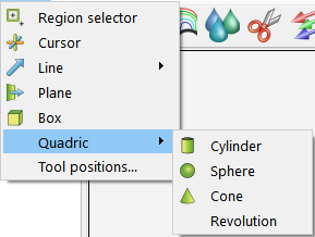
Quadric |
Opens a pull-down menu which allows you to choose one of the Quadric Tools and make it visible. Tools → Quadric
|
|
|
Cylinder Tool Toggle |
Makes the Cylinder Tool visible/invisible in the Graphics Window. The Cylinder Tool appears as thick direction line with center point and center tool axis system, and a circle around the line at the mid and two end points. Thinner projection lines run parallel to the direction line through the three circles outlining the surface of the cylinder. The Cylinder Tool is initially centered about the Look-At point with the direction line pointing in the X direction. There are a number of ways to manipulate the tools either interactively or via the transformation dialog. You can change its length and orientation interactively in the Graphics Window by selecting one of its end points. You can rotate it in the Graphics Window by selecting the end of one of the tool axes. You can change its diameter by selecting the circle about the mid point. You can reposition it interactively in the Graphics Window by selecting its center. You can reposition it precisely using the Transformation Editor by right-clicking on the cylinder tool origin and choosing Edit. |
|
|
Sphere Tool Toggle |
Makes the Sphere Tool visible/invisible in the Graphics Window. The Sphere Tool appears as thick direction line with center point and center tool axis system, and with several circles outlining the sphere. The Sphere Tool is initially centered about the Look-At point with the direction line pointing in the X direction. There are a number of ways to manipulate the tools either interactively or via the transformation dialog. You can change its radius and orientation interactively in the Graphics Window by selecting one of the thick direction line end points. You can rotate it in the Graphics Window by selecting the end of one of the tool axes. You can reposition it interactively in the Graphics Window by selecting its center. You can reposition it precisely using the Transformation Editor by right-clicking on the sphere tool origin and choosing Edit. |
|
| Makes the Cone
Tool visible/invisible in the Graphics Window. The Cone
Tool appears as thick direction line with center point and a tool axis system at
the apex. It has a circle at the opposite end point. Thinner projection lines
run from the beginning point to the circle at the end point outlining the
surface of the cone. The Cone Tool is initially centered
about the Look-At point with the direction line pointing in
the X direction. There are a number of ways to manipulate the tools either
interactively or via the transformation dialog. You can change its length and
orientation interactively in the Graphics Window by selecting one of the thick
direction line end points. You can change its diameter by selecting the largest
circle about the end point. You can rotate it in the Graphics Window by
selecting the end of one of the tool axes. You can reposition it interactively
in the Graphics Window by selecting its center. You can reposition it precisely
using the Transformation Editor by right-clicking on the
cone tool origin and choosing Edit. Note: The cone tool always operates as if the tool extends infinitely from the origin at the half angle. The half angle of the cone tool is in degrees. |
||
|
Revolution Tool Toggle |
Makes the Surface of Revolution Tool visible/invisible in the Graphics Window. The Revolution Tool appears as thick direction line with center point and center tool axis system, and with several circles outlining each user defined point along the tool. Thinner projection lines run through the circles to outline the revolution surface. The Revolution Tool is initially centered about the Look-At point with the direction line pointing in the X direction. There are a number of ways to manipulate the tools either interactively or via the transformation dialog. You can change its length and orientation interactively in the Graphics Window by selecting one of the thick direction line end points. You can rotate it in the Graphics Window by selecting the end of one of the tool axes. You can reposition it interactively in the Graphics Window by selecting its center or alternatively, you can reposition it precisely by specifying coordinates in the Transformation Editor dialog (described in Tool Positions... → Quadric below). Tools → Quadric |
|
|
Transformation Editor Tools Dialog |
The Transformation Editor dialog is used for many types of transformation operations including: global transformations, camera transformations, tool transformations, and others. Tool transformations are described in this section of the documentation. |
|
|
Tool positions... |
Opens the Transformation Editor dialog which allows you to precisely position the various tools within the Graphics Window in reference to the selected Frame. Tools → Tool Positions... |
|
|
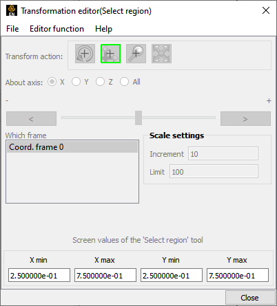
Region Tool (Selection region) |
Click Editor Function in the Transformation Editor dialog and then select Selecting Tools → Region Selector from the Editor Function Menu Bar to display the dialog shown below:
|
|
|
To precisely position the Selection tool, enter the desired normalized screen coordinate values for X and Y minimum and maximum. The coordinates can be between 0.0 and 1.0. Tools → Tool Positions... → Tools → Select region. |
||
|
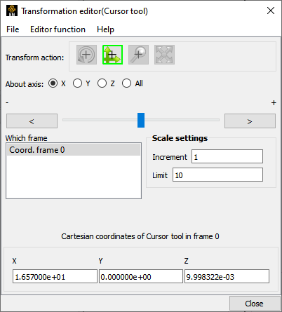
Cursor Tool |
Selecting Tools → Cursor from the Editor Function Menu Bar displays the dialog as shown in figure below. Additionally, right-clicking on the cursor tool itself in the graphics window and selecting Edit... from the Context Sensitive menu also displays this dialog.
|
|
|
The Transformation Editor dialog provides three methods for the precise positioning of the Cursor Tool. First, the Cursor Tool may be positioned within the Graphics Window by entering coordinates in the X, Y, and Z fields. Pressing Return causes the Cursor Tool to relocate to the specified coordinates in the selected Frame (or, if more than one Frame is selected, for Frame 0). |
||
|
It is also possible to reposition the Cursor Tool from its present coordinate position by specific increments. The button allows you to choose the axis of translation (X, Y, Z, or All). The Slider Bar at the top allows you to quickly choose the increment by which to move the position of the Cursor Tool. Dragging the slider in the negative (left) or positive (right) directions and then releasing it will cause the X, Y, and Z coordinate fields to increment as specified and the Cursor Tool to relocate to the new coordinates. The number specified in the Limit field of the Scale Settings area determines the negative (-) and positive (+) range of the slider. If the Limit is set to 1.0 as shown, then the numerical range of the slider bar will be -1 to +1. |
||
|
Alternatively, you can specify an increment for translation in the Increment field of the Scale Settings area. Pressing Enter while the mouse pointer is in the Increment field will cause the Cursor Tool to translate along the specified axis (or all axes) by the increment specified. Transformation Editor → Editor Function → Tools → Cursor. |
||
|
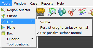
Line Tool |
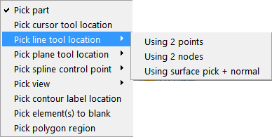
From the menu Tools → Line there are three options as shown in the figure below: Visible, Restrict drag to surface+normal, and Use positive surface normal.
|
|
|
Visible |
Toggles the line tool visibility |
|
|
Restrict drag to surface + normal |
Locks line parallel to selected part’s surface normal. After choosing this option, click on the Pick icon and choose to pick plane tool location using surface pick + normal and then put the cursor tool on the part surface and pick using the P key and the line tool will appear aligned with the surface normal at the point picked with one end attached to the surface at the point of the picking. |
|
|
Use positive surface normal |
Locks line parallel to selected part’s surface normal in direction of surface normal. Therefore the same as above except the line tool will originate at the picked point location, but will be in the direction of the positive normal. |
|
|
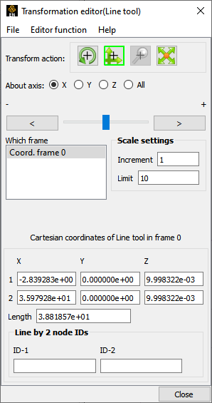
Selecting Tools → Line from the Editor Function menu bar displays the dialog as shown in the figure below. Additionally, right-clicking on the Line Tool in the graphics window and selecting Edit... from the Context Sensitive menu also displays this dialog.
|
||
|
The Transformation Editor can control precisely the position and size of the line tool. |
||
|
Position |
The Transformation Editor dialog provides several methods for the precise positioning of the Line Tool. First, the Line Tool may be positioned within the Graphics Window by entering coordinates for the two endpoints in the X, Y, and Z fields. Pressing return after entering each coordinate value causes the Line Tool to relocate to the specified coordinates in the selected Frame (or if more than one Frame is selected, in Frame 0). Enter all three X, Y, Z fields for a endpoint and then press return once to cause the line tool to update its position to that endpoint. |
|
|
You can also specify the node ID labels to use for the line endpoints. |
||
|
It is also possible to reposition the Line Tool from its present coordinate position by specific increments. First click on the translate icon. The Axis button allows you to choose the axis of translation for the center of the line (X, Y, Z, or All). The Slider Bar at the top allows you to quickly choose the increment by which to move the position of the center point of the Line Tool. Dragging the slider in the negative (left) or positive (right) directions and then releasing it will cause the X, Y, and Z coordinate fields to increment as specified and the Line Tool to relocate to the new coordinates. The number specified in the Limit field of the Scale Settings area determines the negative (-) and positive (+) range of the slider. If the Limit is set to 1.0 as shown, then the numerical range of the slider bar will be -1 to +1. The transformations are relative to the line tool axis system. |
||
|
Alternatively, you can specify an increment for translation in the Increment field of the Scale Settings area. Pressing Enter while the mouse pointer is in the Increment field will cause the center point of the Line Tool to translate along the specified axis (or all axes) by the increment specified. |
||
| Orientation |
First click the rotate icon. Next, pick an axis about which to rotate. Next pick an increment and limit (in degrees) and slide the slider to rotate the plane. |
|
| Scale |
First click the scale icon. Next pick an increment and limit and slide the slider to scale the line about its center, along its length. Transformation Editor → Editor Function → Tools → Line |
|
|
See Use the Line Tool. |
||
|
Plane Tool |
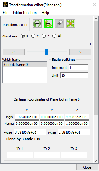
Selecting Tools → Plane from the Editor Function Menu Bar displays the dialog as shown below. Additionally, right-clicking the plane tool in the graphics area and selecting Edit... from the Context Sensitive menu also displays this dialog.
|
|
|
The Transformation Editor can control precisely the position, orientation, and size of the plane tool. |
||
|
Position |
The Transformation Editor dialog provides several methods for the precise positioning of the Plane Tool. First, the Plane Tool may be positioned by entering the Origin, Normal and X- and Y-Size. Second, the Plane Tool may be positioned by entering in 3 node IDs representing 3 corners (assuming unique node IDs). Third, the Plane Tool may be positioned using the Algebraic Plane Equation. Finally, the Plane Tool may be positioned within the Graphics Window by entering coordinates for the three corners of the plane in the X, Y, and Z fields. Corner 1 is defined as the -X, -Y corner of the plane, Corner 2 is defined as the +X, -Y corner of the plane, and Corner 3 is defined as the +X, +Y corner of the plane. Pressing return causes the Plane Tool to relocate to the specified coordinates in the selected Frame (or if more than one Frame is selected, in Frame 0). For your convenience, you can enter values into all fields and then press return once to update the plane tool position. |
|
|
You can also position the Plane Tool be entering the id for three nodes. The Plane Tool will then remain tied to these three nodes - even as the nodes move in a transient geometry model. |
||
|
You can also position the Plane Tool by entering a plane equation in the form Ax + By + Cz = D in the four fields and then pressing Enter. For convenience, enter in all four then press return. The coefficients may then be normalized, but the equation of the plane will be the same as the one you entered. The coefficients of the plane equation are in reference to the selected Frame (or if more than one Frame is selected, to Frame 0). |
||
|
As with the Cursor and Line Tools, it is possible to reposition the Plane Tool from its present coordinate position by specific increments. First click the translate icon at the top of the Transformation Editor. The Axis button allows you to choose the axis of translation (X, Y, Z, or All) for the origin of the Plane Tool (intersection of the axes). The Slider Bar at the top allows you to quickly choose the increment by which to move the position of the origin. Dragging the slider in the negative (left) or positive (right) directions and then releasing it will cause the X, Y, and Z coordinate fields to increment as specified and the origin of the Plane Tool to relocate to the new coordinates. The number specified in the Limit field of the Scale Settings area determines the negative (-) and positive (+) range of the slider. If the Limit is set to 1.0 as shown, then the numerical range of the slider bar will be -1 to +1. |
||
|
Alternatively, you can specify an increment for translation in the Increment field of the Scale Settings area. Pressing Enter while the mouse pointer is in the Increment field will cause the center of the Plane Tool to translate along the specified axis (or all axes) by the increment specified. |
||
|
Orientation |
First click the rotate icon. Next, pick an axis about which to rotate. Next pick an increment and limit (in degrees) and slide the slider to rotate the plane. |
|
|
Scale |
First click the scale icon. Next pick an axis direction to scale (X or Y only). Finally pick an increment and limit and slide the slider to scale the size of the plane. Transformation Editor → Editor Function → Tools → Plane |
|
|
See Use the Plane Tool. |
||
|
Box Tool |
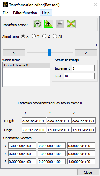
Selecting Tools → Box from the Editor Function Menu Bar displays the dialog shown below. Additionally, right-clicking the graphical Box Tool and selecting Edit... from the Context Sensitive menu also displays this dialog.
|
|
|
The Transformation Editor can control precisely the position, orientation, and size of the box tool. |
||
|
Position |
The Transformation Editor dialog provides several methods for the precise positioning of the Box Tool. First, the Box Tool may be positioned within the Graphics Window by entering coordinates for the origin of the box in the X, Y, and Z fields and the length of the each of the X, Y, and Z sides. Pressing Enter causes the Box Tool to relocate to the specified location in the selected Frame (or if more than one Frame is selected, in Frame 0). For your convenience, you can enter in all of the fields and then press return once to update the Box Tool position. Additionally, you can modify the orientation of the Box Tool by entering the X, Y, and Z orientation vectors of the box axis in regards to Frame 0. |
|
|
As with other Tools, it is possible to reposition the Box Tool from its present coordinate position by specific increments. First click the translate icon at the top of the Transformation Editor. The Axis button allows you to choose the axis of translation (X, Y, Z, or All) for the origin of the Box Tool (intersection of the axes). The Slider Bar at the top allows you to quickly choose the increment by which to move the position of the origin. Dragging the slider in the negative (left) or positive (right) directions and then releasing it will cause the X, Y, and Z coordinate fields to increment as specified and the origin of the Box Tool to relocate to the new coordinates. The number specified in the Limit field of the Scale Settings area determines the negative (-) and positive (+) range of the slider. If the Limit is set to 1.0 as shown, then the numerical range of the slider bar will be -1 to +1. |
||
|
Alternatively, you can specify an increment for translation in the Increment field of the Scale Settings area. Pressing Enter while the mouse pointer is in the Increment field will cause the origin of the Box Tool to translate along the specified axis (or all axes) by the increment specified. |
||
|
Orientation |
First click the rotate icon. Next, pick an axis about which to rotate. Next pick an increment and limit (in degrees) and slide the slider to rotate the Box Tool. |
|
|
Scale |
First click the scale icon. Next pick an axis direction to scale. Finally pick an increment and limit and slide the slider to scale the size of the Box Tool. |
|
|
Transformation Editor → Editor Function → Tools → Box See Use the Box Tool. |
||
|
Cylinder or Sphere Tools |
Selecting Tools and then Cylinder or Sphere from the Editor Function Menu Bar displays the dialog as shown below. Additionally, right-clicking the Cylinder or Sphere tool in the graphics area and selecting Edit... from the Context Sensitive menu also displays this dialog.
|
|
|
The Transformation Editor can control precisely the position and size of the cylinder tool. |
||
|
Position |
The Transformation Editor dialog enables you to precisely control the coordinates of the Cylinder or Sphere Tool origin (center point of the thick direction line) by specifying them in the Orig. X, Y, and Z fields. You control the direction vector for the Cylinder or Sphere Tool direction axes by specifying the coordinates in the Axis X, Y, and Z fields of the selected Frame (or if more than one Frame is selected, in Frame 0). The Radius of each tool may be specified in the Radius Field. |
|
|
It is possible to reposition the Cylinder or Sphere Tool origins by specific increments. First click on the translate icon. The Axis button allows you to choose the axis of translation (X, Y, Z, or All) for the origin of the tool. The Slider Bar at the top allows you to quickly choose the increment by which to move the position of the origin. Dragging the slider it in the negative (left) or positive (right) directions and then releasing it will cause the X, Y, and Z coordinate fields to increment as specified and the origin of the Cylinder or Sphere Tool to relocate to the new coordinates. The number specified in the Limit field of the Scale Settings area determines the negative (-) and positive (+) range of the slider. If the Limit is set to 1.0 as shown, then the numerical range of the slider bar will be -1 to +1. |
||
|
Alternatively, you can specify an increment for translation in the Increment field of the Scale Settings area. Pressing Enter while the mouse pointer is in the Increment field will cause the origin of the Cylinder or Sphere Tool to translate along the specified axis (or all axes) by the increment specified. |
||
|
Orientation |
First click the rotate icon. Next, pick an axis about which to rotate. Next pick an increment and limit (in degrees) and slide the slider to rotate the plane. |
|
|
Scale |
First click the scale icon. Next pick an axis direction to scale. Can only scale in the X (longitudinal) or Y (radial) directions. Finally pick an increment and limit and slide the slider to scale the size of the cylinder or sphere Tool. |
|
|
Transformation Editor → Editor Function → Tools → Cylinder or Sphere See Use the Cylinder Tool and Use the Sphere Tool. |
||
|
Cone Tool |
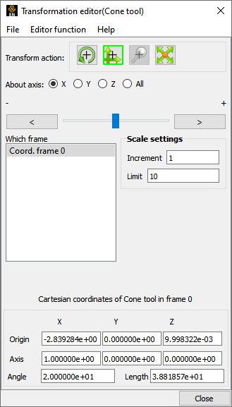
Selecting Tools → Cone from the Editor Function Menu Bar displays the dialog as shown below. Additionally, right-clicking on the graphical Cone Tool and selecting Edit... from the Context Sensitive menu also displays this dialog.
|
|
|
The Transformation Editor dialog enables you to precisely control the coordinates of the Cone Tool origin (the point of the cone) by specifying them in the Origin X, Y, and Z fields. You control the direction vector for the Cone Tool direction axis by specifying the coordinates in the Axis X, Y, and Z fields for the selected Frame (or if more than one Frame is selected, in Frame 0). The conical half angle may be specified in degrees in the Angle Field. |
||
|
Position |
It is possible to reposition the Cone Tool origin by specific increments. The button allows you to choose the axis of translation (X, Y, Z, or All) for the origin of the tool. The Slider Bar at Top allows you to quickly choose the increment by which to move the position of the origin. Dragging the slider in the negative (left) or positive (right) directions and then releasing it will cause the X, Y, and Z coordinate fields to increment as specified and the origin of the Cone Tool to relocate to the new coordinates. The number specified in the Limit field of the Scale Settings area determines the negative (-) and positive (+) range of the slider. If the Limit is set to 1.0 as shown, then the numerical range of the slider bar will be -1 to +1. |
|
|
Alternatively, you can specify an increment for translation in the Increment field of the Scale Settings area. Pressing Enter while the mouse pointer is in the Increment field will cause the center of the Cone Tool to translate along the specified axis (or all axes) by the increment specified. |
||
|
Orientation |
First click the rotate icon. Next, pick an axis about which to rotate. Next pick an increment and limit (in degrees) and slide the slider to rotate the plane. |
|
|
Scale |
First click the scale icon. Next pick an axis direction to scale. Can only scale in the X (longitudinal) or Y (half conical angle) directions. Finally pick an increment and limit and slide the slider to scale the size of the cone tool. |
|
|
Transformation Editor → Editor Function → Tools → Cone See Use the Cone Tool. |
||
|
Revolution Tool |
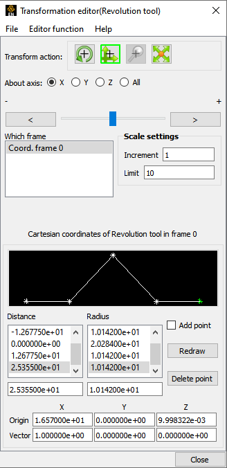
Selecting Tools → Revolution from the Editor Function Menu Bar displays the dialog as shown below. Additionally, right-clicking on the graphical Revolution Tool and selecting Edit... from the Context Sensitive menu also displays this dialog.
|
|
|
For the Revolution Tool, you not only control the origin and direction vector, but the number of points and positions that are revolved about the axis. The desired coordinates of the Revolution Tool origin (center point of the thick direction line) are specified in the Origin X, Y, and Z fields. The direction vector for the Revolution Tool direction axis is specified by entering the desired coordinates in the Vector X, Y, and Z fields for the selected Frame (or if more than one Frame is selected, in Frame 0). |
||
|
Additional points may be added to the Revolution Tool by clicking on the Add Point(s) toggle and then clicking at the desired location in the schematic for the tool. There is no need to be overly precise in its placement since its location can be modified. Once you have added all of the new points you wish, the Add Point(s) toggle should be turned off. |
||
|
A point may be deleted by selecting it in the schematic area and then clicking the button. |
||
|
The position of any point may be modified interactively within the Revolution Tool schematic window, Simply click and drag the point to the desired location. The precise location of any point may be specified by selecting the point in the schematic with the mouse and then entering the desired Distance (from the Revolution Tool origin) or Radius (from the axis) for the point in the text entry fields beneath the Distance and Radius Lists. Pressing Enter will enter the new value in the list above for the selected point. |
||
|
The Transformation Editor can control precisely the position and size of the revolution tool. |
||
|
Position |
It is possible to reposition the Revolution Tool origin by specific increments. First click on the translate icon. The button allows you to choose the axis of translation (X, Y, Z, or All) for the origin of the tool. The Slider Bar at the top allows you to quickly choose the increment by which to move the position of the origin. Dragging the slider in the negative (left) or positive (right) directions and then releasing it will cause the X, Y, and Z coordinate fields to increment as specified and the origin of the Revolution Tool to relocate to the new coordinates. The number specified in the Limit field of the Scale Settings area determines the negative (-) and positive (+) range of the slider. If the Limit is set to 1.0 as shown, then the numerical range of the slider bar will be -1 to +1. |
|
|
Alternatively, you can specify an increment for translation in the Increment field of the Scale Settings area. Pressing Enter while the mouse pointer is in the Increment field will cause the center of the Revolution Tool to translate along the specified axis (or all axes) by the increment specified. |
||
|
Orientation |
First click the rotate icon. Next, pick an axis about which to rotate. Next pick an increment and limit (in degrees) and slide the slider to rotate the plane. |
|
|
Scale |
First click the scale icon. Next pick an axis direction to scale. Can only scale in the X (longitudinal) or Y (radial) directions. Finally pick an increment and limit and slide the slider to scale the size of the revolution tool. |
|
|
Redraw |
This button will cause the Revolution Tool schematic window to re-center to the currently defined points of the tool. |
|
|
Transformation Editor → Editor Function → Tools → Revolution |
||
|
Spline Tool |
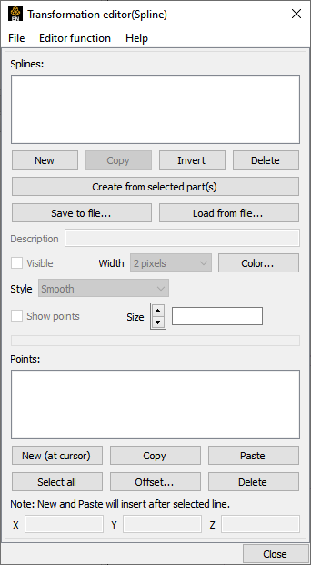
Selecting Tools → Spline from the Editor Function Menu Bar displays the dialog as shown below. Additionally, right-clicking on the Spline tool in the graphics area and selecting Edit... form the Context Sensitive menu also displays this dialog.
|
|
|
The Transformation Editor dialog enables you to create and edit the control points for a spline. A spline is used for one of three functions (a) path for a camera, (b) the path for a clip plane, and (c) the path for a distance vs. variable query. |
||
|
|
Creates a new spline |
|
|
|
Creates a new spline by copying the selected spline |
|
|
|
Inverts the control points for the selected spline |
|
|
|
Delete the selected spline(s) |
|
|
|
Save the selected spline(s) to a file |
|
|
|
Load splines from a file |
|
|
|
Create a new spline and use all of the coordinates in the selected parts as the control points. |
|
|
Description |
Description of the spline |
|
|
Visible |
Toggles spline visibility |
|
|
Width |
Line width for the spline |
|
|
|
Brings up the color chooser dialog to set the color for the spline |
|
|
Show points |
Toggles the visibility of the control points. |
|
|
Size |
The size of the control point markers in model coordinates |
|
|
Points |
The list of control points for the spline. Right click operations in this list include New, Copy, Paste, and Delete |
|
|
|
Inserts a new control point in the selected spline after the selected point (or if no points are selected or exist at the end of the list) using the cursor tool as the location. |
|
|
|
Selects all of the points in the list |
|
|
|
Stores the coordinates of the selected points in preparation for a Paste operation |
|
|
|
Paste the copied points and insert them immediately after the selected point (or if no points are selected or exist then at the end of the list). |
|
|
|
Brings up a dialog where a xyz offset value can be specified. The offset is added to the coordinates of the selected points. |
|
|
|
Delete the selected points. |
|
|
Shows the XYZ values for the selected point. If modified will change the control point location. |
||