


The Fourier Transformation method applies the phase shifted boundary conditions illustrated in Figure 4.3: Phase Shifted Periodic Boundary Conditions in a more direct method than in the Time Transformation method.
It basically consists of attempting to directly "impose" a phase shift between the R1,R2 boundaries and the S1,S2 boundaries for the primitive variables of the problem. A direct method of applying the phase shift boundary method was proposed by Erdos [215] but his method requires storage of the signal for a complete period on all the R1/R2 S1/S2 boundaries including the interface shared by the rotor and stator sections. The Frequency Transformation method makes use of temporal Fourier series decomposition Equation 4–14 to avoid storing the signal on the S1/S2 and R1/R2 boundaries. This method was initially introduced by He [218].
 | (4–14) |
In this method the signal is decomposed into harmonics of the
fundamental frequency  of each passage. For
example in typical TRS problems this fundamental frequency is the
inverse of the blade passing period
of each passage. For
example in typical TRS problems this fundamental frequency is the
inverse of the blade passing period  ,
where:
,
where:
 | (4–15) |
For other use cases the blade passing period can be calculated as :
For an inlet disturbance case using
 from Inlet Disturbance Case in the CFX-Solver Modeling Guide.
For a blade flutter case using
 from Application of Phase-Shifted Boundaries to a Blade Flutter Case in the CFX-Solver Modeling Guide.
Along similar lines as Gerolymos [216] the rotor/stator interface can be further decomposed as
a signal in theta harmonics resulting in a double ( -
- ) Fourier
series method Equation 4–16.
) Fourier
series method Equation 4–16.
 | (4–16) |
By decomposing the signal on pitch-wise periodics with temporal
Fourier series and decomposing the signal on the rotor/stator interface
with double Fourier series we take advantage of an excellent data
compression method by making use of the periodic nature of the flow
since only the Fourier coefficients  and
and  need to be stored to reconstruct the flow
at an arbitrary time and pitchwise location once the transient periodicity
regime is
reached.
need to be stored to reconstruct the flow
at an arbitrary time and pitchwise location once the transient periodicity
regime is
reached.
The Fourier Transformation method in Ansys CFX is implemented using a double-passage method. The data is collected at the (implicit) interface (R2,S2) between the two passages, Figure 4.5: Double Passage Method. While performance is case dependent, the double-passage approach converges in fewer cycles than a single-passage method, owing to the superior quality of the data update (Fourier data is collected at the internal interface between passages, where the solution is fully implicit and far from the actual periodic boundaries). The double-passage Fourier Transformation approach converges very rapidly to a quasi-periodic state, requiring as few as 3-4 cycles in some cases.
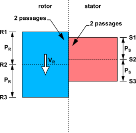
Figure 4.6: Inlet Disturbance Configuration illustrates how the time shift is applied for the Double Passage Fourier Transformation method.
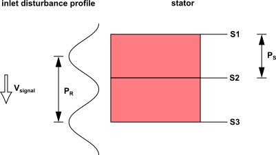
The time shift is:

The signal  on S1 is equal to the signal on S2 phase shifted
by
on S1 is equal to the signal on S2 phase shifted
by


The signal  on S3 is equal to the signal on S2 phase shifted
by
on S3 is equal to the signal on S2 phase shifted
by

:

Where  is the reconstructed signal at S2 using the accumulated
Fourier coefficients on that same boundary.
is the reconstructed signal at S2 using the accumulated
Fourier coefficients on that same boundary.
For modeling information, see Fourier Transformation in the CFX-Solver Modeling Guide.