Note: For terminology and abbreviations used in this document, please refer to Transient Blade Row Modeling Terminology in the CFX-Solver Modeling Guide.
Transient blade row flow can be modeled using the Transient Rotor Stator frame change model. However, transient turbomachinery flow calculations are computationally demanding because they often require modeling the entire turbomachine geometry due to the unequal number of blades from one row to another. In order to reduce the computational effort (resulting in a faster calculation) the problem setup can be made on a reduced model of the turbomachine. This model reduction can be accomplished if pitch-change methods such as PT, TT, or FT are used. The reduction in size of the computational domain reduces memory requirements (by a factor of 1/number of passages) and results in faster solution convergence to a steady-periodic state.
In addition, the time-marching solution methods are traditionally used to obtain the final steady-periodic state. Time marching methods require integration over several blade passing periods before the solution reaches steady-periodic conditions. The integration of the transient periodic flow can be further accelerated by solving the flow problem using the Harmonic Analysis (HA) method. This chapter introduces the Ansys CFX pitch-change methods for transient blade row modeling the Harmonic Analysis solution method.
Pitch Change in a Blade Row
Using conventional methods for modeling transient rotor-stator applications, it is often the case that prohibitive computing resources are required to obtain detailed accurate simulations.
Figure 4.1: One passage periodicity cannot be applied illustrates how conventional periodicity is inadequate when trying to use one passage to model a simulation that has a non-unity pitch ratio.
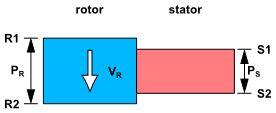
Figure 4.2: Workaround using standard periodicity shows the workaround needed in using a conventional pitch scaling (profile transformation) approach. For the pitch scaling approach, you must replicate passages on both sides of the interface to reduce the pitch scale ratio to unity. Since most systems have prime number of components, you need to model all the passages. This can be very costly and might require the simulation of the entire wheel in turbo-machinery applications if the number of blades on one of the sides is a prime number.
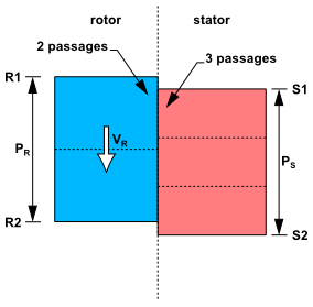
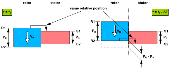
Figure 4.3: Phase Shifted Periodic Boundary Conditions illustrates
the common principle used in two of the Transient Blade Row methods: Time Transformation and Fourier Transformation. Each of these methods achieves what are effectively "phase
shifted" periodic conditions through very different approaches.
The basic principle of a phase-shifted periodic condition is that
the pitch-wise boundaries R1/R2 and S1/S2 are periodic to each other
at different instances in time. For example the relative position
of R1 and S1 at  is reproduced between sides R2 and S2 at an earlier
time
is reproduced between sides R2 and S2 at an earlier
time  where
where  is defined by
  . Here
  and
and  are the rotor
and stator component pitches, respectively, and
are the rotor
and stator component pitches, respectively, and  is the velocity of the rotor.