Unlike the Time Transformation pitch-change method, the Fourier Transformation pitch-change method does not have any known limitations on the pitch ratio (or nodal diameter for a blade flutter application) and works with both compressible and incompressible flows.
The Fourier transformation method can be used in cases involving:
Rotational flow boundary disturbances
Blade flutter (or forced response)
Transient rotor stator interactions (single stage only)
Note: See Fourier Transformation in the CFX-Solver Theory Guide for more theoretical information about the Fourier Transformation method.
The basic procedure for setting up a Transient Blade Row model is outlined in Setting up a Transient Blade Row Model. For simulations involving the Fourier Transformation model:
Each turbo component requires two instances of the passages that constitute a repeatable section. A GGI interface must be created to join the two instances. This domain interface will be selected as the sampling interface. A phase-shifted periodic domain interface connection is required on the outer periodic boundaries. This periodic interface is selected when defining the phase corrected interface. See Fourier Transformation Disturbance Settings in the CFX-Pre User's Guide for a description of the sampling domain interface.
For a given domain, optionally add one disturbance to the list of disturbances.
Those transient rotor stator interfaces not referenced by a disturbance will be treated with the Profile Transformation method.
All periodic and sampling interface pairs must use the
Bitmapintersection method. The option that controls the intersection method is found in CFX-Pre in the details view for the domain interface, on the Basic Settings tab, under Mesh Connection Method > Mesh Connection > Intersection Control. For periodic and sampling interface pairs, theBitmapmethod takes effect when the Intersection Control check box is cleared. When the Intersection Control check box is selected, the Option setting is set toBitmapby default.The Transient Rotor Stator interface must use the
Directintersection method. The option that controls the intersection method is found in CFX-Pre in the details view for the domain interface, on the Basic Settings tab, under Mesh Connection Method > Mesh Connection > Intersection Control. For a Transient Rotor Stator interface, theDirectmethod takes effect when the Intersection Control check box is cleared. If you select the Intersection Control check box, you must change the Option setting (from its default value ofBitmap) toDirect.Ensure that no disturbance signal has a speed of zero relative to the component on which that signal acts.
When solving a simulation that involves the Fourier Transformation method (including the steady-state simulation for initialization), the use of double precision is strongly recommended for accuracy and robustness.
Some inlet boundaries might be required to have identical conditions, depending on the geometry. The same applies for outlet boundaries.
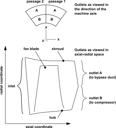
Consider a geometry as viewed in axial-radial space, with the axial coordinate measuring distance along the machine axis and the radial coordinate measuring distance from the machine axis. As viewed in this space, boundaries that overlap must have identical specified conditions. Boundaries that do not overlap, including those that only meet at a point, can have different specified conditions.
For example, consider the outlets in Figure 6.1: Example Fan Geometry as viewed in axial-radial space. Outlet A of passage 1 and outlet A of passage 2 overlap, so must have identical specified conditions. Similarly, outlet B of passage 1 and outlet B of passage 2 overlap, so must have identical specified conditions. Outlet A (of any passage) and outlet B (of any passage) do not overlap, so can have different specified conditions.