


The following topics concerning analysis details and solution controls for this problem are available:
The solution parameters used in this model are input as follows:
nlgeom,on                  ! specifies geometric nonlinearity
time,1                     ! end time
ncnv,2                     ! continues analysis after failure via rezoning and multiframe restart
rescontrol,define,all,1    ! makes restart files available
outres,all,all
nsubst,20,2000,10          !
Rezoning requires a static analysis with geometric nonlinearity (NLGEOM,ON).
The end time is 1. The initial, minimum, and maximum time step sizes are 20, 2000, and 10, respectively; they are applied with an initial time step size of 0.05 and a minimum time increment of 0.5e-3.
Because the program execution ends if the analysis fails to converge, the analysis is continued after failure by performing rezoning and a multiframe restart. (Without the NCNV command, running the full analysis in batch mode would not be possible due to analysis termination after the first divergence.)
All restart files must be available; otherwise, it is impossible to know which
substeps to perform to initiate the rezoning. It is also a good idea to save the
results; doing so makes it easier to investigate the reason for solution termination
and decide which substep to use to activate rezoning. If it is not possible to save
results (due to disk space limitations, for example), they can be generated for a
specific substep from the restart files
(ANTYPE,,REST,Loadstep,Substep,RSTCREATE).
The general rezoning process for vertical rezoning, horizontal rezoning, or a combination of both is the same. Following are helpful techniques for applying rezoning specifically to a ring-gear forging problem:
Selecting the best substep to initiate rezoning is the crucial factor in the rezoning process. No unique selection criteria can be applied universally to all rezoning problems. Various substep-selection techniques can be used for the initial rezoning or subsequent ones.
Generally, the best way to select a substep is by visual inspection of results in the postprocessing module (/POST1). It is helpful to use the most important element solutions (PLESOL) to create animation files that capture the specific moment when the mesh becomes sufficiently distorted, but not yet severely distorted (that is, when internal angles approach or exceed 180 degrees).
It is good practice to correlate the element solutions plots with corresponding steps in the monitor file (.mntr) and the convergence pattern in general. To initiate rezoning, select a substep where the current time increment is not close to the specified minimum and where the convergence pattern of the solution has not slowed down significantly (before bisections have started to occur).
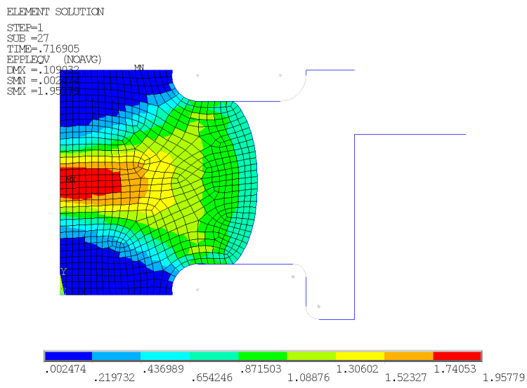
In this example, no more than two rezonings are needed because the initial divergence occurs close to the end of analysis (TIME = 0.96). The initial rezoning cannot be performed very close to the end of the last converged substep, because another rezoning is planned before the end of the solution. If the initial rezoning is performed at the beginning of the analysis, large subsequent deformations distort the refined mesh too early in the process, necessitating more vertical rezonings.
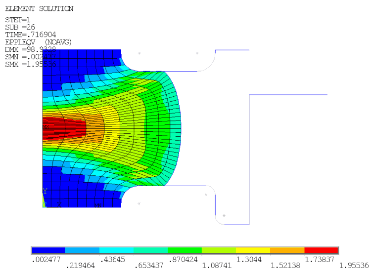
In this case, substep 26 (TIME = 0.716) is chosen because of the results and monitor file examinations. Although this substep has fewer convergence difficulties than the original solution, experimentation shows that some substeps close to substep 26 may also be good candidates for the first rezoning step.
In the following figure, the element solution of effective plastic strains at this stage shows the deformed mesh, where some of the elements exhibit a very high aspect ratio and internal angles close to 180 degrees:
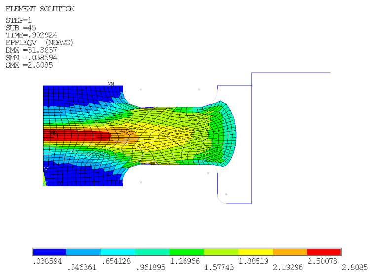
For the second rezoning, the selection technique changes somewhat because the deformation is more pronounced. The strain gradients are larger, and the mapping of variables is more difficult, than in the first rezoning. It is necessary, therefore, to perform the next rezoning as close as possible to the end time so that after restart, the analysis can continue to completion. Often, this technique involves a few trial-and-error iterations to isolate the optimal substep for rezoning.
Substep 47 (TIME = 0.9138) or thereabouts appears to be best suited for remeshing from the perspective of limited element distortions. The final selection of substep 45 (TIME = 0.9s) as the optimal substep, however, is guided by the convergence from the prior balancing of the residual forces (MAPSOLVE).
Element distortions guide the general range of substeps best suited for remeshing. The residual-force balancing determines the precise substep.
After selecting the substep, the region to be remeshed must be selected (typically an easier task than the substep selection process).
Generally, if the model is too large or too complex or if the mesh distortion is localized, horizontal (multiple) remeshing is a better option than remeshing the entire model.
If the model is not large or the mesh distortion is widely spread as in this problem, the entire model can be selected for remeshing.
Horizontal rezoning may be necessary depending on the model size, computational costs, and the degree of accuracy required.
A region selected for remeshing should contain all of the highly distorted elements and, if possible, should be slightly larger than the area containing the distorted elements. The only condition is that all regions must be of the same element type, material type, thickness (for plane stress), and nodal coordinate system (except for boundary nodes).
Generating an improved mesh by remeshing is the key to successful rezoning. To improve convergence, the new mesh should have better shape characteristics than the old mesh. To avoid mapping difficulties, the size of the new mesh should not be changed drastically. Retaining the same element size (ESIZE) in the new mesh can work, provided that the new element connections and topology reflect better shape characteristics.
The new mesh can be:
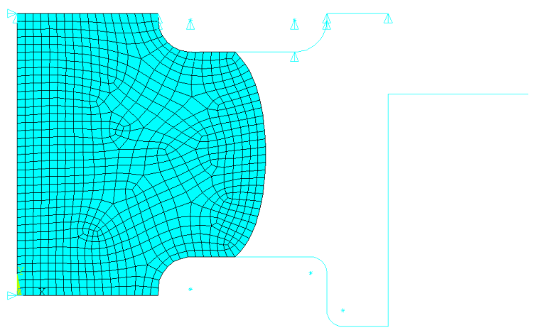
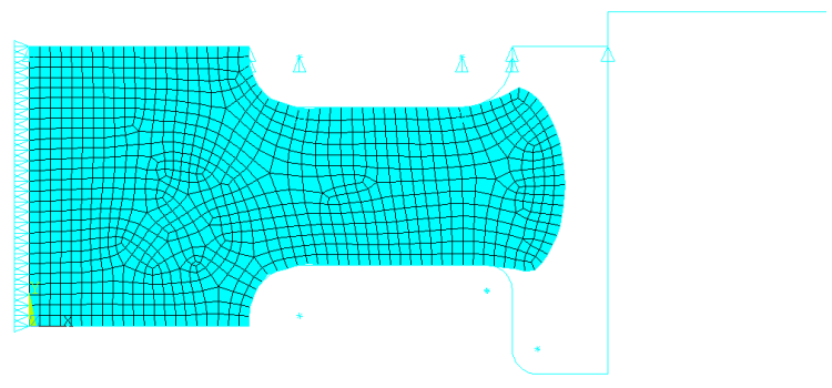
For this problem, a new mesh generated as a .cdb file is read in (REMESH,READ). The new mesh contains only solid elements, as the contact elements are generated automatically when remeshing is complete (REMESH,FINISH).
The rigid target elements remain the same throughout the analysis and cannot be remeshed. While it is possible for the new mesh to contain contact and target information as well, it is faster and more reliable to read in only the remeshed solid elements and allow the contact/target elements to be generated automatically.
The initial element size is approximately 4. The first rezoning decreases it by a factor of two, and the second rezoning uses an element size of 1.7. The new meshes appear in Figure 4.4: New Mesh Read in During the First Rezoning and Figure 4.5: New Mesh Read in During the Second Rezoning
Mesh Size Affects Mapping
The quality of the new mesh, and the mapping operation in general, can be sensitive to mesh size. If the mesh quality is mediocre due to a less-than-optimal element size, mapping difficulties may occur, leading to convergence failure. In such cases, a better mesh using a different element size is necessary.
After remeshing, the solution is mapped automatically from the old mesh to the new mesh (MAPSOLVE). The mapping operation introduces extra substeps to balance the residual forces and achieve equilibrium.
Although the default is five substeps, it is generally better to use more substeps, especially when contact is included in the problem. This problem uses 500 substeps as the maximum in the case of convergence problems becoming an issue. Using a larger number of substeps does not affect computational efficiency and is recommended for solving nonlinear problems characterized by large strains.
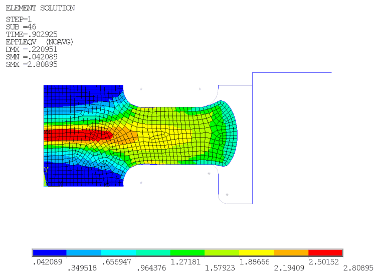
The results of the element solution of effective plastic strains after the first and second mapping are shown in the following two figures. The results are compared with the same plots before mapping (as shown in Figure 4.2: Effective Plastic Strain and Deformed Mesh at Time of First Rezoning and Figure 4.3: Effective Plastic Strains and Deformed Mesh at Time of Second Rezoning).
If the old mesh is heavily distorted by rezoning, or if the differences in mesh density and topology between the old and new mesh are especially large (specifically in the elements on boundaries), mapping variables may become difficult, possibly resulting in errors or convergence failure.
If mapping leads to a successful convergence despite the distortion, the results may be slightly different than those which existed before mapping. To observe this effect, compare Figure 4.2: Effective Plastic Strain and Deformed Mesh at Time of First Rezoning to the following figure
Convergence issues after mapping often indicate that the restarted analysis will also have convergence difficulties; therefore, if mapping uses many substeps to achieve equilibrium, try to rezone from an earlier substep or improve the quality of the new mesh.
After each rezoning, the analysis is continued by performing a standard multiframe restart, provided that all necessary files are available. During restart, the number of substeps can be adjusted to achieve better convergence.
The following input shows the vertical rezoning process as described for this problem:
/clear,nostart
/file,ringforging

/solu                              ! First rezoning at substep 26 (time = 0.716)
rezone,manual,1,26
remesh,start
remesh,read,mesh1,cdb              ! Read in the first mesh with esize = 2
allsel,all
remesh,finish
mapsolve,500,pause
finish
/solu                              ! First multiframe restart
antype, , rest, , , continue
solve
finish
/clear,nostart
/file,ringforging

/solu                              ! Second Rezoning at substep 45 (time = 0.9)
rezone,manual,1,45
remesh,start
remesh,read,mesh2,cdb              ! Read in the second mesh with esize=1.7
allsel,all
remesh,finish
mapsolve,500,pause
finish
/solu                              ! Second multiframe restart
antype, , rest, , , continue
solve
finish