


The following figure shows one-quarter of the model, all that is necessary for this analysis:
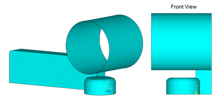
The geometry of the block is 1/4 of the full geometry of the block shown in Figure 27.1: Hot-Rolling Model. Appropriate geometries for the rollers are also considered in the quarter model.
Geometry of the block is created in DesignModeler and meshed with SOLID185 (with mixed u-P formulation (KEYOPT(6) = 1)) elements. The following figure shows the dimensions and mesh of the block:
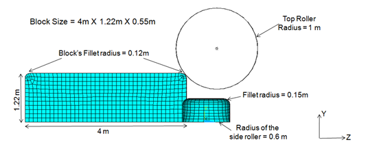
Notice that the block has small fillets at either end of the top face. The fillet helps to establish contact with the top roller. Without the fillet, the sharp corner of the block would cause local singularities, and the analysis would diverge.
Dimensions for both roller pairs are shown in Figure 27.4: Meshed Model with Dimensions. The rollers are modeled as rigid target surfaces.
Two methods are available for creating rigid target surfaces:
Generate Target Elements via Primitives
Use this method if the shape of the target surface matches any of the available primitives (circle, cylinder, cone, and sphere). You can also combine primitive segments with general segments (lines, parabolas, triangles, and quadrilaterals) to define a target surface.
You must first specify the shape of the target elements (TSHAP), then define the radius via real constants. Create nodes (N) and elements (E) directly. The elements will have their shapes already defined.
Mesh the Areas with TARGE170 Target Elements
Use this method when target surfaces cannot be modeled with primitives. Because the side rollers have fillets at either end, they cannot be modeled using primitives. In this case, CAD geometry of the side roller is created in DesignModeler and then meshed with TARGE170 elements to create the contact pair with the block.
For more information, see Defining the Target Surface in the Contact Technology Guide.
The following two contact pairs are created:
A standard rigid-flexible contact pair is created between the top roller and the block. As shown in the following figure, four faces of the block are contact surfaces:
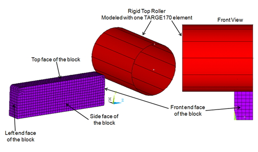
The contact surfaces are modeled via CONTA174 elements.
The rigid top roller is modeled using one TARGE170 element and primitives (TSHAP, CYLI).
One pilot node is created and associated with the top roller (the rigid target surface). The pilot node governs the motion of the entire target surface. (Think of a pilot node as a sort of handle for the rigid target surface.) Forces/moments or rotations/displacements for the entire target surface should generally be specified via the pilot node. The location of the pilot node is important when rotation or moment loading is required. In this case, the pilot node is created at the center of the mass of the top roller, as the roller must be rotated in the second load step.
Example 27.1: Modeling the Contact Pair – Block and Top Roller
The augmented Lagrangian algorithm is used in this contact pair.
et,2,CONTA174
KEYOPT,2,10,2 ! Select option to update contact stiffness in each iteration
et,3,TARGE170

cmsel,s,tn.cnt     ! Select the nodal component of 4 faces of the block
nplot
type,2             ! Select element type 2 (CONTA174)
real,3             ! Use Real Constant 3
esurf              ! Generate contact elements
allsel,all

! Model rigid top roller with primitives

n,9997,0.55,1.85,0.30      ! Create two nodes to define the axis of the cylinder
n,9998,-1.55,1.85,0.30

tshap,cyli                 ! Select “Cylinder” primitive shape
type,3                     ! Select element type 3 (TARGE170)
real,3                     ! Use same real constant 3
r,3,1                      ! Define Radius = 1 m
e,9997,9998                ! Generate one element, cylindrical shaped top roller

! Create and attach pilot node to this rigid target surface (top roller)
type,3
real,3
n,9999,-0.5,1.85,0.30
tshap,pilot
e,9999
allsel,all
A standard rigid-flexible contact pair is created between the side roller and the block. As shown in the following figure, the contact pair is created between two faces (front and side faces) of the block and side rollers:
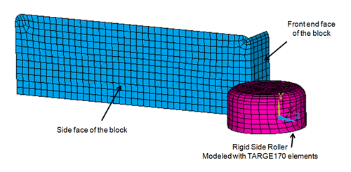
Contact surfaces are modeled with CONTA174 elements and the rigid side roller is modeled with TARGE170 elements. As with the previous contact pair, one pilot node is created at the center of the mass of the side roller. The pilot node governs the motion of the side roller.
Example 27.2: Modeling the Contact Pair – Block and Side Roller
et,4,CONTA174
KEYOPT,2,10,2 ! Select option to update contact stiffness in each iteration
et,5,TARGE170
cmsel,s,tn2.cnt      ! Select the nodal component of 2 faces of the block
nplot
type,4               ! Select element type 4 (CONTA174)
real,5               ! Use Real Constant 5
esurf                ! Generate contact elements
allsel,all
! Model rigid side roller by meshing the area of side roller
type,5               ! Select element type 5 (TARGE170)
real,5               ! Use same real contact 5
aatt,1,5,5           ! Assign attributes to the areas of side roller
amesh,all            ! Mesh geometry of the side roller with TARGE170 elements
allsel,all
esel,s,type,,5       ! The target normals are not oriented correctly, so we must
                     ! reverse the direction of normals
esurf,,reverse       ! Reverse the direction of the normals on target elements
allsel,all
! Create and attach pilot node to this rigid target surface (side roller)
type,5
real,5
n,20999,-0.4461,0.4337,0.0456
tshap,pilot
e,20999
allsel,all