Modeling of this problem involves the following steps:
The coil has a radius of 0.3 mm, and the wire has a 0.05 mm radius with a 0.0125mm initial gap between the filars.
Case 1: Five layers of solid helical coils are created and meshed with SOLID186 elements; see (a) in the figure below.
Case 2 and Case 3: A line model of helical coils is created and meshed with BEAM189 elements; see (b) in the figure below.
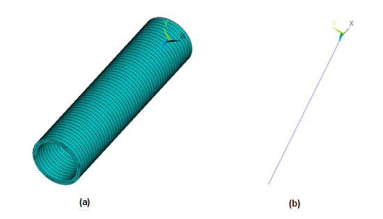
The tube is 3.45 mm long with an outer radius of 0.43 mm and an inner radius of 0.36 mm.
Case 1 and Case 2: A full three-dimensional model of the tube is created and meshed with SOLID186 elements; see (a) in the figure below.
Case 3: A line model of the tube is created and meshed with PIPE289 elements; see (b) in the figure below.
Two contact pairs are defined to simulate contact behavior in the model:
Contact between the coil and the inner tube surface is modeled differently for the three cases, as described below.
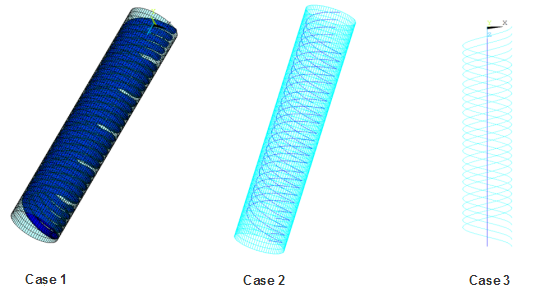
Case 1: Surface-to-surface contact is used. The outer surface of the multi-filar coil is meshed with CONTA174 contact elements, and the inner surface of the tube is meshed with TARGE170 target elements.
Case 2: Line-to-surface contact is used. The multi-filar coil is meshed with CONTA177 contact elements, and the inner surface of the tube is meshed with TARGE170 target elements.
Case 3: Line-to-line (beam-to-beam) contact is used. The multi-filar coil is meshed with CONTA177 contact elements, and the tube is meshed with TARGE170 target elements.
The following non-default contact settings are used.
CONTA177 elements (Case 2 and Case 3):
KEYOPT(3) = 2 to include all contact scenarios, including internal crossing beam-to-beam contact and beam-to-surface contact.
KEYOPT(14) = 2 to define multiple target segments interacting with each contact detection point.
TARGE170 elements (Case 3):
KEYOPT(9) = 1 to define internal beam-to-beam contact
Self contact between the filar surfaces is modeled differently for the three cases, as described below.
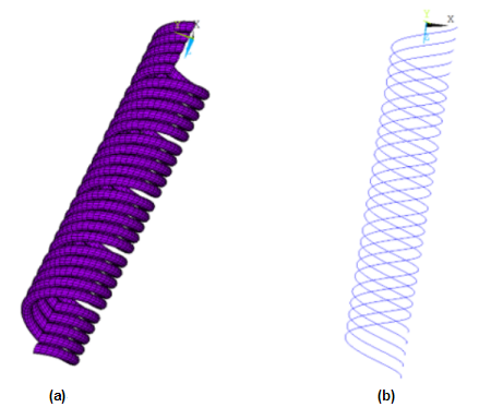
Case 1: Self contact between the coil filars is modeled as surface-to-surface contact. The outer surface of the multi-filar coil is meshed with both CONTA174 contact elements and TARGE170 target elements; see (a) in the figure below.
Case 2 and Case 3: Self contact between the coil filars is modeled as parallel line-to-line contact. The multi-filar coil is meshed with both CONTA177 contact elements and TARGE170 target elements; see (b) in the figure below.
The following non-default contact settings are used.
CONTA177 elements (Case 2 and Case 3):
KEYOPT(3) = 1 to define parallel beam-to-beam contact.
KEYOPT(14) = 2 to define multiple target segments interacting with each contact detection point.


