Modeling is a two-part task, as described in these topics:
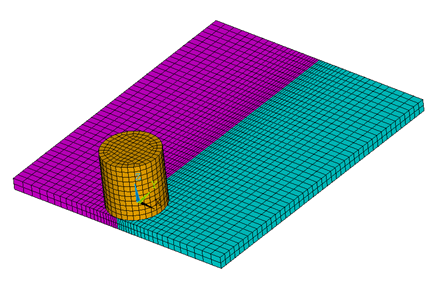
Two rectangular shaped plates (similar to those used in the reference model) are used as the workpiece. Dimensions have been reduced to decrease the simulation time.
The plate size is 3 x 1.25 x 0.125 in (76.2 x 31.75 x 3.18 mm). The tool shoulder diameter is 0.6 in (15.24 mm).
Plate thickness remains the same as that of the reference model, but the plate length and width are reduced. The plate width is reduced because the regions away from the weld line are not significantly affected by the welding process, and this example focuses primarily on the heat generation and temperature rise in the region nearest the weld line.
The height of the tool is equal to the shoulder diameter. Both the workpiece (steel plates) and the tool are modeled using coupled-field element SOLID225 with the structural-thermal option (KEYOPT(1) = 11).
A hexahedral mesh with a low-order element is used because the presence of midside nodes (or quadratic interpolation functions) can lead to oscillations in the thermal solution, leading to nonphysical temperature distribution. A hexahedral mesh is used instead of a tetrahedral mesh to avoid mesh-orientation dependency. For more accurate results, a finer mesh is used in the weld-line region. The following figure shows the 3D meshed model:
Contact is modeled as follows for the FSW simulation:
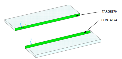
During the simulation, the surfaces to be joined come into contact. A standard surface-to-surface contact pair using TARGE170 and CONTA174, as shown in the following figure:
The surface-projection-based contact method (KEYOPT(4) = 3 for contact elements) is defined at the contact interface. The surface-projection-based contact method is well suited to highly nonlinear problems that include geometrical, material, and contact nonlinearities.
The problem simulates welding using the bonding capability of contact elements. To achieve continuous bonding and simulate a perfect thermal contact between the plates, a high thermal contact conductance (TCC) of 2E06 W/m2 °C is specified. (A small TCC value yields an imperfect contact and a temperature discontinuity across the interface.) The conductance is specified as a real constant for CONTA174 elements.
The maximum temperature ranges from 70 to 90 percent of the melting temperature of the workpiece material. Welding occurs after the temperature of the material around the contacting surfaces exceeds the bonding temperature (approximately 70 percent of the workpiece melting temperature). In this case, 900 °C is considered to be the bonding temperature based on the reference results. The bonding temperature is specified using the real constant TBND for CONTA174. When the temperature at the contact surface for closed contact exceeds the bonding temperature, the contact type changes to bonded. The contact status remains bonded for the remainder of the simulation, even though the temperature subsequently decreases below the bonding value.
Example 28.1: Defining the Contact Settings of the Contact Pair
et,6,TARGE170
et,7,CONTA174
keyopt,7,1,1        ! Displacement and Temp DOF
keyopt,7,4,3        ! To include Surface projection based method

rmodif,6,14,2e06    ! A real constant TCC, thermal contact
                    ! conductance coeff. b/w the plates, W/m2°C
rmodif,6,35,1000    ! A real constant TBND,bonding temp for
                    ! welding, °C
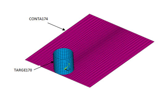
The tool plunges into the work piece, rotates, and moves along the weld line. Because the frictional contact between the tool and workpiece is primarily responsible for heat generation, a standard surface-to-surface contact pair is defined between the tool and workpiece. The CONTA174 element is used to model the contact surface on the top surface of the workpiece, and the TARGE170 element is used for the tool, as shown in this figure:
Two real constants are specified to model friction-induced heat generation. The fraction of frictional dissipated energy converted into heat is modeled first; the FHTG real constant is set to 1 to convert all frictional dissipated energy into heat. The factor for the distribution of heat between contact and target surfaces is defined next; the FWGT real constant is set to 0.95, so that 95 percent of the heat generated from the friction flows into the workpiece and only five percent flows into the tool.[2]
A low TCC value (10 W/m2 °C) is specified for this contact pair because most of the heat generated transfers to the workpiece. Some additional heat is also generated by plastic deformation of the workpiece material. Because the workpiece material softens and the value of friction coefficient drops as the temperature increases [3], a variable coefficient of friction (0.3 to 0.15) is defined (TB,FRIC with TBTEMP and TBDATA).
Example 28.2: Specifying the Settings for the Contact Pair
et,4,TARGE170
et,5,CONTA174
keyopt,5,1,1          ! Displacement & Temp DOF
keyopt,5,5,3          ! Close gap/reduce penetration with auto cnof
keyopt,5,9,1          ! Exclude both initial penetration or gap
keyopt,5,10,2         ! Contact stiffness update each iteration based


rmodif,5,9,500e6      ! Max friction stress, N/m2
rmodif,5,14,10        ! Thermal contact conductance b/w tool and
                      ! workpiece, W/m2'C
rmodif,5,15,1	        ! A real constant FHTG,the fraction of
                      ! frictional dissipated energy converted
                      ! into heat
rmodif,5,18,0.95      ! A real constant  FWGT, weight factor for
                      ! the distribution of heat between the
                      ! contact and target surfaces
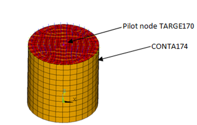
The workpiece remains fixed in all stages of the simulation. The tool rotates and moves along the weld line. A pilot node is created at the center of the top surface of the tool in order to apply the rotation and translation on the tool. The motion of the pilot node controls the motion of the entire tool. A rigid surface constraint is defined between the pilot node (TARGE170) and the nodes of the top surface of the tool (CONTA174). A multipoint constraint (MPC) algorithm with contact surface behavior defined as bonded always is used to constrain the contact nodes to the rigid body motion defined by the pilot node.
The following contact settings are used for the CONTA174 elements:
To include MPC contact algorithm: KEYOPT(2) = 2
For a rigid surface constraint: KEYOPT(4) = 2
To set the behavior of contact surface as bonded (always): KEYOPT(12) = 5