


The element formulation for the concrete is based on SOLID185 linear brick elements with simplified enhanced strain formulation (KEYOPT(2) = 3). The solid geometry is meshed with 30 elements in each horizontal direction and 4 elements over the depth of the concrete slab.
The steel armoring is modeled using a smeared continuum approach and shares the same nodes as the surrounding concrete:
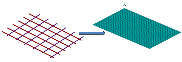
The reinforcing elements are modeled using two additional discrete geometrical areas located at depth hr. For each additional area, a surface mesh is generated (MESH200).
The smeared reinforcing area is defined (SECTYPE,REINF,SMEAR), followed by the associated equivalent thickness and reinforcing spacing data (SECDATA).
The local directions of the reinforcing fibers are defined via local element reference coordinate systems (LOCAL) for the generated MESH200 elements.
Finalizing the defined reinforcing (EREINF) generates smeared reinforcing of the specified REINF265 section based on the MESH200 elements and the existing SOLID185 elements.
Example 49.1: Defining a Smeared Reinforcing Section in the x Direction
! Generate mesh-only elements of type MESH200 for the reinforcement in x direction
SECTYPE,2,REINF,SMEAR
Asx = 3.14/4*6E-3*6E-3 ! diameter 6 mm
dx = 0.25      ! m
SECDATA,2,Asx,dx,12,0,MESH
Example 49.2: Defining Reinforcing Location and Orientation
ET,2,200
KEYOPT,2,1,6
KEYOPT,2,2,0
ESYS,12
TYPE,2
SECNUM,2
MAT,2
! Generate reinforcement location area that is offset from bottom surface and mesh it with elements of type MESH200.
asel,s,loc,y,-pD
AOFFST,ALL,-toffset
*GET,myarea2,AREA,,NUM,MAX
asel,s,area,,myarea2
esize,1,
AMESH,ALL
Additional reinforcing in the z direction is defined in the same way.
After defining the mesh-only elements (MESH200), the smeared reinforcing elements are generated automatically (EREINF) for both reinforcing directions.
Example 49.3: Generating the Smeared Reinforcing Elements
! Generate reinforcement elements based on mesh200 elements type 2 and 3
CSYS,0
esel,s,type,,2
cmsel,a,ereinf185
EREINF
ESEL,S,ENAME,,REINF265
CM,reinf_x_elems,ELEM

esel,s,type,,3
cmsel,a,ereinf185
EREINF
ESEL,S,ENAME,,REINF265
CMSEL,U,reinf_x_elems
CM,reinf_z_elems,ELEM
The generated reinforcing elements can be displayed if desired (EPLOT).
Example 49.4: Displaying the Generated Reinforcing Elements
! Display generated reinforcing elements
esel,s,ename,,solid185
/trlcy,elem,0.9
esel,a,ename,,reinf265
/dev,vect,1
/psymb,layr,-1
eplot
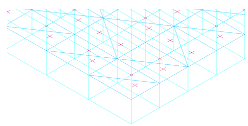
The reinforcing elements residing on top of the bottom layer are in the form of triangular elements. The working direction of each reinforcing section corresponds to the x direction of each local coordinate system (indicated by a red line).
With finalized discretization of the reinforced concrete slab, the load is applied.
The in situ dead load is generated by applying a gravitational acceleration of g = 9.81 m/s2 in the y direction. A load-limit analysis is then performed.
A surface-pressure load is applied on the top-surface of the concrete slab and subsequently increased until the load limit is reached.
The load limit is marked by a loss of numerical convergence, also identifiable as the horizontal tangent of the resulting load/displacement curve.