


The dimensions of the concrete slab considered here are 6m x 4m x 0.2m.
The structure is affected by both its dead load and a surface-pressure load. The surface-pressure load is increased until failure occurs.
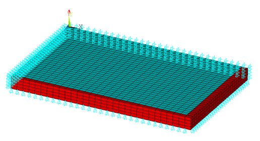
The border of the structure is supported in the vertical y direction. Due to symmetry conditions, it is possible to simplify the model. The finite element model includes the symmetry boundary conditions on the cutting planes of the resulting quarter model:
The slab is composed of concrete as the base matrix material incorporating a steel grid reinforcing structure to absorb stresses that might develop under bending movement.
The reinforcing grid lies at a depth of hr = 0.17 m. The armoring has an equivalent distribution area of Asx = 1.13 cm2/m in the x direction, and Asz = 1.88 cm2/m in the orthogonal z direction. The distance between successive reinforcing elements (each having a diameter of 6 mm) is Δdx = 0.25 m for elements acting in the global x direction and Δdz = 0.15 m for elements acting in the global z direction.
The influence of the reinforcing is incorporated into the simulation model via reinforcing elements using a smeared continuum mechanics approach (REINF265). The placement and orientation of the armoring is incorporated using mesh-independent reinforcing based on mesh-only elements (MESH200).
To account for the boundary singularities resulting from the idealized vertical support conditions, the first element layer that connects to the support is defined as linearly elastic (shown in red).