Following are the modeling topics available for this problem:
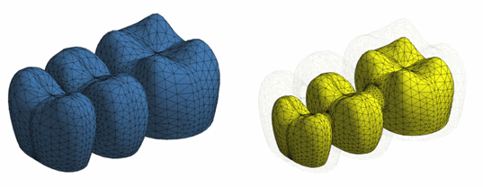
For both the veneer and core meshes, thermal element SOLID87 is used for the transient thermal analysis, as shown in this figure:
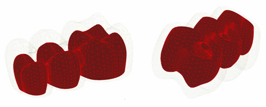
A 3D surface-to-surface contact is used for creating the contact pair. The contact between veneer and core is meshed with CONTA174 and TARGE170 elements, as shown in the following figure:
The temperature profile (obtained in the thermal analysis) is used in a nonlinear structural analysis to determine the residual stress in the veneer. The temperature results are read in as thermal loads at different time steps (LDREAD).
The structural analysis requires the same mesh as that used for the thermal analysis. It is therefore necessary to change the thermal elements to structural elements (ETCHG). In this case, thermal element SOLID87 is converted to structural solid element SOLID187. The contact CONTA174 and target TARGE170 elements are compatible with SOLID187, so those elements remain; contact element options are modified as necessary (KEYOPT).
The following example input changes the element type:
ETCHG,TTS               ! Change thermal elements to structural elements
KEYOPT,3,1,0            ! Change degrees of freedom for TEMP to UX, UY, and UZ
The FPD model contains 164,041 nodes. The model has 110,275 3D 10-node tetrahedral structural solid elements (56,811 veneer elements and 53,464 core elements), and 10,568 3D 8-node surface-to-surface contact elements.
Bonded surface-to-surface contact pairs define the contact between the veneer and the core. The contact pair modeled for the thermal analysis is converted for the structural analysis (ETCHG).
The following example input creates the element pair:
/COM, CONTACT PAIR CREATION - START
ET,3,170               ! Define TARGET170 element
ET,4,174               ! Define CONTACT174 element
KEYOPT,4,1,2           ! Select temperature degree of freedom for thermal analysis
REAL,3                 ! Set the element real constant
RMODIF,3,14,4e-005     ! Define Thermal Contact Conductance (TCC)

! Generate the target surface
NSEL,S,,,VENEER.TGT    ! Selected user-defined nodal component for target
TYPE,3                 ! Element type for target elements
ESLN,S,0               ! Select elements attached to nodal component
ESURF                  ! Generate target mesh on the free faces of selected elements
ALLSEL,ALL

! Generate the contact surface
NSEL,S,,,CORE.CNT      ! Selected user-defined nodal component for contact
TYPE,4                 ! Element type for contact elements
ESLN,S,0               ! Select elements attached to nodal component
ESURF                  ! Generate contact mesh on the free faces of selected elements
ALLSEL
/COM, CONTACT PAIR CREATION - END


