


There are two ways to transfer loads and/or deformations from Adams to Mechanical APDL:
If the component is assumed to be rigid in Adams, you can transfer joint and external forces, accelerations, and rotational velocity acting on the component as described in Transferring Loads on a Rigid Body.
If the component is flexible, you can transfer the deformed shape of the component using the MSR toolkit from Adams. This type of transfer is not supported by the Ansys-Adams Interface. See Transferring the Loads of a Flexible Body for more information on this transfer method.
If you model your component as a rigid body in Adams, you can use the Export FEA Loads feature in Adams to export the loads to a file. This file can then be imported into Mechanical APDL for a subsequent stress analysis.
If you model your component as a flexible body, Adams allows you to use the Export FEA Loads feature to transfer the loads, but the loads will be incomplete. Therefore, this load transfer procedure should generally not be used for flexible bodies. The transfer of loads may work, however, if the flexible bodies experience only small dynamic effects. If this is not the case, you may want to change the component temporarily to a rigid body (using the Modify utility in Adams) and run another simulation before you transfer the loads.
After performing an Adams simulation, you can export loads on a specific component at specific times. In Adams, select to access the Adams Export FEA Loads dialog box.
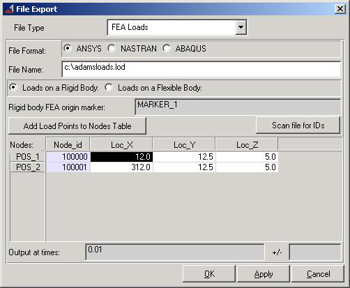
Complete the following steps in this dialog box.
File Type: Select FEA Loads
File Format: Select Ansys
File Name: Specify a name for the load file. The default extension is .lod.
Specify whether you want to export loads on a rigid body or a flexible body.
Rigid body: You must define a marker on the body that has the same position and orientation relative to the body as the global origin does in the Mechanical APDL model.
Flexible body: The marker is set automatically since this information is known from the .mnf file.
Click "Add Load Points to Nodes Table."
If you chose a rigid body, you can input the node IDs of the nodes where the loads have to be applied in Mechanical APDL.
If you chose a flexible body, Adams automatically inputs the correct node IDs.
Output at times: Specify at what time steps you want to export the loads.
Finally, Adams will ask you about the units. The units for export must be the same as those chosen for building the Mechanical APDL model. If they are not the same, change them temporarily to the Mechanical APDL units or scale the loads in the load file later.
Every time step in Adams is treated as a load step in Mechanical APDL. In Adams versions up to 11.0.0, Adams writes the LSWRITE command before the load commands. Therefore, if you are using Adams version 11.0.0 or earlier, you must use a text editor to move the LSWRITE command to the end of each time step in the .lod file.
The following loads will be included in the load file:
After exporting the load file from Adams, you can use the Ansys-Adams Interface to import the load file and initiate a static structural analysis. To access the Import from Adams dialog box, pick:
Complete the following steps in the dialog box:
Import file from Adams: Enter the name of the load file that was exported from Adams.
Import option: Theoretically, external forces and inertia forces are in equilibrium. Due to numerical errors or due to mass discrepancies between Adams and Mechanical APDL, this is insufficient to prevent a rigid-body motion of the component. Hence, you must constrain the component against rigid-body motion in order to do a static structural analysis. The Ansys-Adams Interface offers two import options to achieve this.
Import loads only. The program applies inertia loads and external forces to the structure according to the load file. For this option, you must manually add constraints to the Mechanical APDL model that are compatible with the constraints used in the Adams model (if possible), or use common engineering sense to prevent rigid-body motion.
Add weak springs: The program adds weak springs (COMBIN14 elements) to the corners of the bounding box of the component. (For more information, see the WSPRINGS command documentation). The weak springs prevent rigid-body motion without influencing the stress results. (See Adding Weak Springs for more information on how the program adds weak springs to the model.)
Import button: When you pick the Import button, one load step file is written per time step exported from Adams; existing load step files are deleted. If you chose the "Import loads only" option, you will have to start the static solution manually by issuing the SOLVE command for each load step. If you chose the "Add weak springs" option, inertia relief is activated (IRLF,1) to compute accurate acceleration loads, and the static analysis is started automatically.
Note: If you use the import procedure a second time with the "Add weak springs" option, additional weak springs will be added to the model. This will have only a small influence on the results.
If you prefer to work in batch mode, you may choose to import the load file and initiate the solution by command input. After exporting the load file from Adams, use the following commands to read the load file and initiate the static solution.
/INPUT,...              ! Read the load file from Adams
WSPRINGS (or D)         ! Apply weak springs (or use D commands to
                        ! apply rigid-body constraints)
*DO,par,ival,fval,inc   ! Specify load steps to solve
  IRLF,1                ! Activate inertial relief to achieve higher accuracy
                        ! (this step is optional)
  LSREAD,par            ! Read load step
  SOLVE                 ! Solve model
*ENDDO
Every subsequent call of the WSPRINGS command will apply weak springs. Therefore, this command may be omitted when importing new loads.
When the structural analysis is complete, you review the results as you would for any linear structural analysis.
When using the weak springs option with inertia relief check that:
The accelerations that Mechanical APDL calculated computed for inertia relief are small compared to the applied acceleration loads from Adams (ACEL, OMEGA, DOMEGA). Issue the command IRLIST to view the inertia relief accelerations (translational and rotational).
The forces in the springs are small compared to the external forces. The forces in the springs can be viewed by listing the reaction forces. Use the PRRSOL command to list reaction forces.
The external forces have to be balanced by the applied inertia forces only. If one of the above is not true, there is an imbalance in your model that must be removed. Check your Mechanical APDL and Adams models, respectively.
If you want to model a flexible component in the Adams program and perform a subsequent stress analysis, you may want to use the Modal Stress Recovery (MSR) toolkit provided by Mechanical Dynamics, Inc. Using the features of this toolkit, it is possible to transfer the loads of a flexible component from Adams to Mechanical APDL for stress analysis. This toolkit provides several strategies for interfacing with Mechanical APDL:
Export Time-Domain Displacements: If you have only a few time steps to analyze, this is a fast option. The displacement of every node of the component is written directly into a Mechanical APDL input file. This file can then be imported using the /INPUT command. A simple static analysis can be started in Mechanical APDL after the import of this file.
Export Mode Shapes: The toolkit writes a Mechanical APDL input file that can be used to compute the orthonormalized or unorthonormalized eigenmodes of the component. By using the Export of Modal Coordinates option, these eigenmodes can be scaled in Mechanical APDL, and the stresses in the component can be computed for every time step.
Export Nodal Loads: Using this feature, you can write a Mechanical APDL input file to perform stress recovery as a superposition of unit force load steps. This method ignores the inertia load contribution to the flexible body deformation, so it may be inaccurate when interpreting dynamic effects.
Note: The MSR toolkit features described here are not supported by the Ansys-Adams Interface.