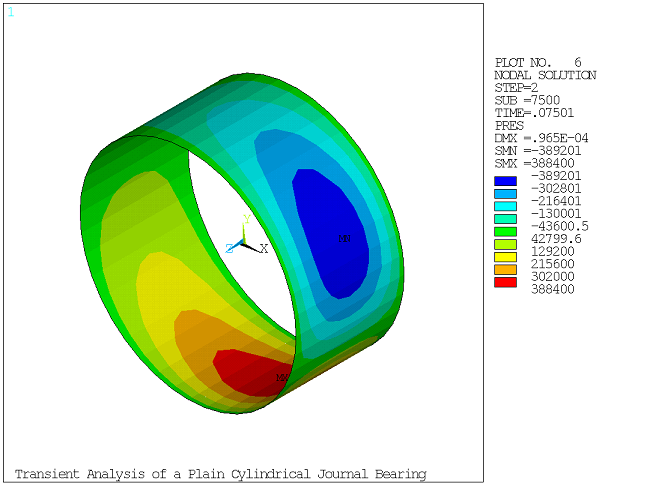
The simple model of the bearing is described in Example: Transient Analysis of a Plain Cylindrical Journal Bearing where a 2D approach is used. In this example, a 3D model is created with SOLID185 and FLUID218 elements. The rotational velocity is applied to the shaft part using pilot nodes (MPC contacts) on the rear and front faces.
The mesh is coarse and a nonlinear large-deflection transient analysis is performed. In the first load step, the loads are applied gradually (KBC,0) and a very small time step is used to ease the convergence. Default force and pressure-based convergence criteria are specified (CNVTOL).
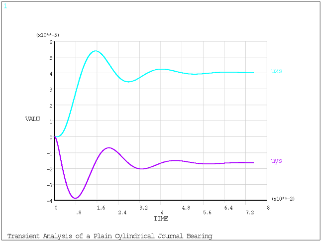
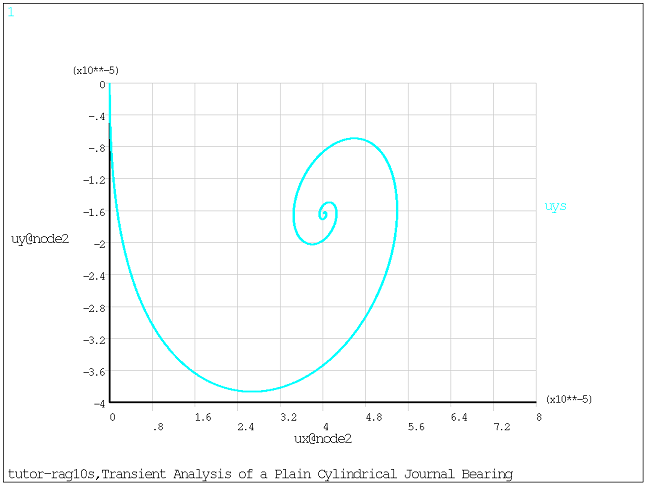
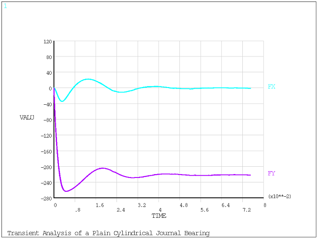
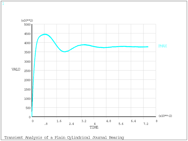
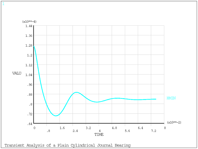
The variation of the position of the shaft center, bearing forces, maximum pressure, and minimum film thickness as a function of time is obtained.
/TITLE, Transient Analysis of a Plain Cylindrical Journal Bearing
! ** Main parameters
lshaft                = 2.54e-2
rshaft                = lshaft
mshaft              = 22.7
omgshaft_rpm = 4000
xclear              = 1.27e-4
mu                   = 0.069

! ** Secondary parameters
pi             = 4*atan(1)
l2             = lshaft/2
omgshaft = omgshaft_rpm*pi/30
roshaft     = mshaft/(lshaft*pi*rshaft**2)
zedge      = -l2

/prep7

! ** Solid Element
et,1,185
mp,ex,1,2.0e13
mp,nuxy,1,0.33
mp,dens,1,roshaft
mp,betd,1,0.1

! ** Geometry and Solid Mesh
cylind,0,rshaft, -l2,l2, 0  ,90
ndvlz = 10        ! longitudinal lines divisions
lesiz,7,,,ndvlz
lesiz,8,,,ndvlz
lesiz,9,,,ndvlz
ndvrd = 5         ! radial lines divisions
lesiz,1,,,ndvrd
lesiz,6,,,ndvrd
lesiz,2,,,ndvrd
lesiz,5,,,ndvrd
ndvcr = 10        ! arc lines divisions
lesiz,3,,,ndvcr
lesiz,4,,,ndvcr
type,1
mat,1
vsweep,all
vsymm,x,all
vsymm,y,all
nummrg,node
nummrg,kp

! ** MPC on Rear Face
*get,numn,NODE,0,NUM,MAX
numn = numn + 1
*get,nume,ELEM,0,NUM,MAX
nume = nume + 1
*set,tid,4
*set,cid,5
et,cid,174
et,tid,170
keyo,tid,2,1               ! Don't fix the pilot node
keyo,tid,4,111111
keyo,cid,12,5              ! Bonded Contact
keyo,cid,4,2               ! Rigid CERIG style load
keyo,cid,2,2               ! MPC style contact
type,cid
mat ,cid
real,cid
nsel,,loc,z,-l2
esln
esurf
*set,_npilot1,numn
n,_npilot1,0,0,-l2
type,tid
tshape,pilo
en,nume,_npilot1
tshape
allsel

! ** MPC on Front Face
*get,numn,NODE,0,NUM,MAX
numn = numn + 1
*get,nume,ELEM,0,NUM,MAX
nume = nume + 1
*set,tid,6
*set,cid,7
et,cid,174
et,tid,170
keyo,tid,2,1                ! Don't fix the pilot node
keyo,tid,4,111111
keyo,cid,12,5              ! Bonded Contact
keyo,cid,4,2                ! Rigid CERIG style load
keyo,cid,2,2                ! MPC style contact
type,cid
mat ,cid
real,cid
nsel,,loc,z,l2
esln
esurf
*set,_npilot2,numn
n,_npilot2,0,0,l2
type,tid
tshape,pilo
en,nume,_npilot2
tshape
allsel

! ** Bearing Element and Mesh
et,3,218
keyopt,3,1,1            !  U + PRES dofs
mp,visc,3,mu
r,3, xclear, rshaft
rmore, zedge
type,3
mat,3
real,3
csys,1
nsel,,loc,x,rshaft
esln
esurf
csys,0
allsel

! ** Boundary Conditions
nsel, ,loc,z,-l2
nsel,a,loc,z,l2
d, all, pres, 0.0d0      ! zero pressure at both ends
nsel, ,node,,_npilot1
nsel,a,node,,_npilot2
d, all, uz, 0.0d0,,,, rotx,roty    ! pilot nodes constraints
allsel
finish

! ** Transient Analysis
/solu
antype, transient
nlgeom,on
outres,all,all

nbdt1 = 10
dt1 = 1e-6
deltim, dt1
time, nbdt1*dt1
acel,, 9.81                         ! gravity
nsel, ,node,,_npilot1
nsel,a,node,,_npilot2
d, all, OMGZ, omgshaft   ! rotational velocity at pilot nodes
allsel
kbc,0
cnvtol,PRES              ! add default pressure criterion
cnvtol,F,,,,1.0            ! specify MINREF
cnvtol,FLOW,-1        ! remove fluid flow criterion
cnvtol,M,-1               ! remove moment criterion
solve

nbdt2 = 7500
dt2 = 1e-5
deltim, dt2
tend = nbdt1*dt1 + nbdt2*dt2
time, tend
kbc,1
solve
finish

/post1
/show,png,rev
/view,,1,1,1

! ** Bearing forces - Maximum Pressure - Minimum Thickness
nbdt = nbdt1 + nbdt2
*dim,fxtab,array,nbdt
*dim,fytab,array,nbdt
*dim,pmaxtab,array,nbdt
*dim,hmintab,array,nbdt
esel,,type,,3
*get,nelem,ELEM,0,COUNT
*do,iloops,1,nbdt

   *if,iloops,gt,nbdt1,then
      set,2,iloops-nbdt1
   *else
      set,1,iloops
   *endif

   f1 = 0
   f2 = 0
   pmax = 0
   hmin = xclear
   ielem = 0
   *do,iloop,1,nelem
      ielem = ELNEXT(ielem)
      *get,con,ELEM,ielem,NMISC,11
      f1 = f1 + con
      *get,con,ELEM,ielem,NMISC,12
      f2 = f2 + con
      *get,con,ELEM,ielem,NMISC,10
      *if,con,gt,pmax,then
         pmax = con
      *endif
      *get,con,ELEM,ielem,NMISC,9
      *if,con,lt,hmin,then
         hmin = con
      *endif
   *enddo
   fxtab(iloops)   = f1
   fytab(iloops)   = f2
   pmaxtab(iloops) = pmax
   hmintab(iloops) = hmin

*enddo
/out,
*status
/out,scratch
finish

/post26
nos = node(0,0,0)         ! shaft center
nsol,2,nos,u,x,uxs
nsol,3,nos,u,y,uys
plvar,2,3
xvar,2
/axlab,x,ux@node2
/axlab,y,uy@node2
plvar,3
/reset
xvar,0

vput,fxtab,4,0.0,,FX
vput,fytab,5,0.0,,FY
vput,pmaxtab,6,0.0,,PMAX
vput,hmintab,7,0.0,,HMIN

plvar,4,5
plvar,6
plvar,7
/out,
prvar,4,5,6,7
/out,scratch
finish

/post1
set,last
esel,,type,,3
plnsol,pres
finish
/exit,nosave