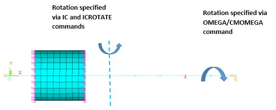
The following example shows a quasi-static analysis of a two rotor system. In this analysis, the gyroscopic forces are included as a load vector. They are calculated from the gyroscopic matrix, generated from the rotational velocity input (OMEGA and CMOMEGA) and the activation of the CORIOLIS command, and from the instantaneous velocities, specified using IC and ICROTATE commands.
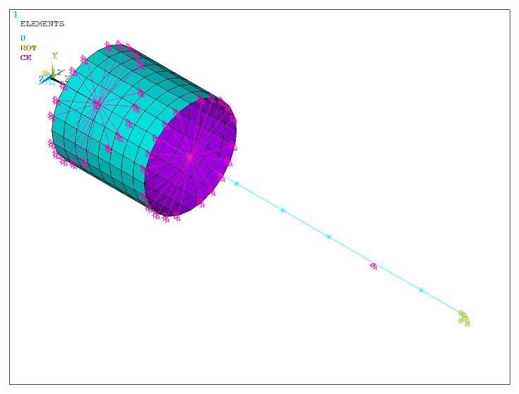
The structure is a two rotor system on symmetric bearings as shown in Figure 7.36: Multi-Rotor System. The rotors, meshed using beam elements, are rotating at 1000 RPM and 2000 RPM respectively about its axis (global X-direction). The stator is meshed using shell elements. Parts are assembled using constraint equations (CERIG and RBE3). The whole structure is also rotating in a direction perpendicular to the shaft axis (global Z-direction), specified using the ICROTATE command.
The shafts nodes are rotated along the local z-direction aligned with the global X-direction. The instantaneous nodal velocities are specified along the local x-direction for both shafts using the IC command.
| Rotational velocity of shaft 1 = 1000 RPM |
| Rotational velocity of shaft 2 = 2000 RPM |
The centrifugal force due to the ICROTATE command definition along the global Z-direction is included in the analysis.
/out,scratch
/prep7

LOCAL,12,0,0,0,0,0,0,90
CSYS,0

! ** ROTOR 1

ET,1,188
SECTYPE,1,BEAM,CSOLID
SECDATA,0.1

MP,EX,1,2E11
MP,NUXY,1,0.3

k,1,0,0,0
k,2,9,0,0
l,1,2
lesize,all,,,9

TYPE,1
SECNUM,1
MAT,1
lmesh,all

CSYS,12
nrotate,all
CSYS,0

! ** ROTOR 2

ET,2,188
SECTYPE,2,BEAM,CSOLID
SECDATA,0.05

MP,EX,2,2E11
MP,NUXY,2,0.3

k,3,2,0,0
k,4,7
l,3,4
lesize,all,,,5

TYPE,2
SECNUM,2
MAT,2
lmesh,all

CSYS,12
nrotate,all
CSYS,0

! ** SHELL CASING

ET,3,181
SECTYPE,3,SHELL
SECDATA,0.1

MP,EX,3,1E11
MP,NUXY,3,0.3
MP,DENS,3,7800

CSYS,12
WPCSYS,-1
CYLIND,1,,1,3

TYPE,3
SECNUM,3
MAT,3
AMESH,3,4
CSYS,0
ALLSEL

! ** DISK MASS 1
ET,4,21
KEYOPT,4,2,0
R,4,75,75,75,125,125,250

TYPE,4
REAL,4
MAT,4

E,6
E,8
E,10

! ** DISK MASS 2
ET,5,21
KEYOPT,5,2,0
R,5,50,50,50,100,100,200

TYPE,5
REAL,5
MAT,5

E,13
E,15

! ** BEARING 1
N,1000,9,0,0
CSYS,12
nrotate,all
CSYS,0

ET,6,14
KEYOPT,6,2,1   ! >> along X direction
R,6,1E7

TYPE,6
REAL,6
MAT,6
E,2,1000

ET,7,14
KEYOPT,7,2,2  ! >> along Y direction
R,7,1E7

TYPE,7
REAL,7
MAT,7
E,2,1000

! ** BEARING 2
LSEL,S,,,3,6
NSLL
RBE3,3,ALL,ALL
ALLSEL

! ** BEARING 3
LSEL,S,,,7,10
NSLL
RBE3,13,ALL,ALL
ALLSEL

! ** BEARING 4
CERIG,9,12,UX,UY

! ** BOUNDARY CONDITIONS
D,1,ux
D,1,uy
D,1,uz
D,1,rotz

D,1000,ALL  ! >> grounded

! ** COMPONENTS DEFINITIONS
ESEL,S,TYPE,,1
ESEL,A,TYPE,,4
CM,ROT_1,ELEM
ALLSEL

ESEL,S,TYPE,,2
ESEL,A,TYPE,,5
CM,ROT_2,ELEM
ALLSEL,ALL,ALL
FINISH

! ** STATIC ANALYSIS
/solu
antype,static
coriolis,on,,,on,,on      ! last field for rotor mass summary printout

cmomega,ROT_1,1000,,,nx(1),ny(1),nz(1),nx(2),ny(2),nz(2)
cmomega,ROT_2,2000,,,nx(11),ny(11),nz(11),nx(12),ny(12),nz(12)

kbc,1

cmsel,s,ROT_1
nsle
ic,all,omgx,1.0   ! ** rotating about global Z (local x)
allsel,all

cmsel,s,ROT_2
nsle
ic,all,omgx,1.0   ! ** rotating about global Z (local x)
allsel,all

icrotate,all,1.0,4,0,0,4,0,1  ! ** axis of rotation passing though 				     ! ** node 6 along z - direction

outres,all,all
/out,
solve
finish

/post1
set,last
rsys,0
cmsel,s,ROT_1
cmsel,a,ROT_2
nsle
/out,
/com, ------------------------------------------------------------
/com, Response UX is due to the centrifugal force.
/com, Response UZ and ROTY are due to the gyroscopic moment.
/com, ------------------------------------------------------------
prnsol,dof
/out,scratch
/view,,1,1,1
/show,png,rev
plnsol,u,x		! ** response due to centrifugal force
plnsol,u,z		! ** response due to gyroscopic moment
/show,close
finish

/exit,nosave
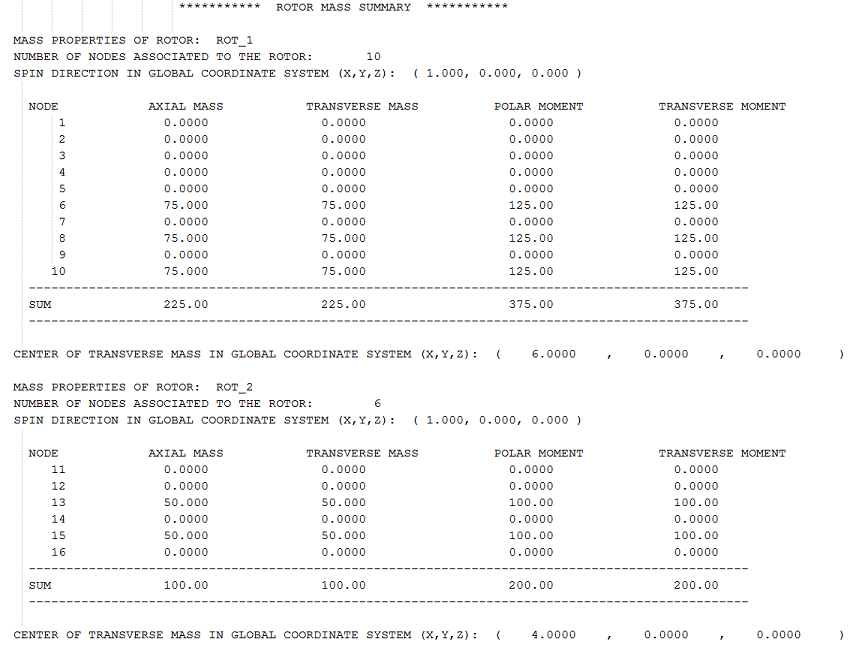
In this example, both rotors are massless. Masses are concentrated at nodes 6, 8, and 10 for rotor 1, and 13 and 15 for rotor 2. The mass information for both rotors can be viewed using the rotor mass summary printout as shown below:
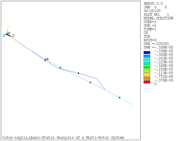
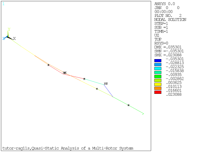
The results of the quasi-static analysis, postprocessed in /POST1, are shown in Figure 7.38: Displacement of the Shafts Along X-Direction Due to Centrifugal Force and Figure 7.39: Displacement of the Shafts Along Z-Direction Due to Gyroscopic Moment.