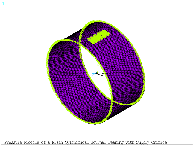
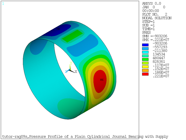
The model is a plain cylindrical journal bearing with full leakage at both ends and rectangular supply orifice at 85° supporting a shaft rotating at 3000 RPM. The pressure profile is calculated at the adimensional equilibrium position XX = 0.4, YY = 0.4. The FLUID218 element is used in a static analysis. Element size is small to capture the variation of the pressure for each degree.
The bearing properties are as follows:
Clearance: 2.5 x 10⁻⁵ m
Length: 0.02 m
Radius: 0.02 m
Viscosity: 0.01 Pa˙s
Supply characteristics:
Pressure: 0.5 x 10⁶ Pa
Orifice height: 10°
Orifice width: ¼ of the diameter
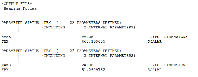
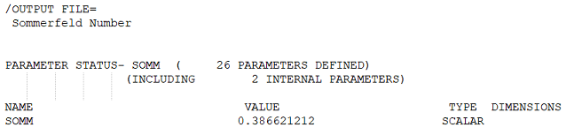
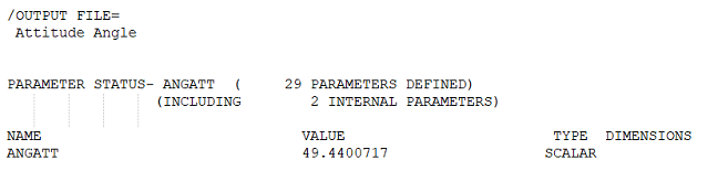
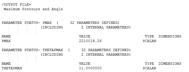
/title, Pressure Profile of a Plain Cylindrical Journal Bearing with Supply Orifice

! ** Main Parameters
rshaft       = 20e-3
lshaft       = 20e-3
omgshaft_rpm = 3000
XX           = 0.4
YY           = 0.4
xclear       = 25e-6
mu           = 0.01
Psup         = 0.5e+6

! ** Secondary Parameters
pi = 4*atan(1)
l2 = lshaft/2
l4 = lshaft/4
omgshaft = omgshaft_rpm*pi/30

/prep7
! ** SOLID185 (unused) - to support FLUID218 mesh only
et,1,185
mp,ex,1,1.0
mp,nuxy,1,1.0
mp,dens,1,1.0

! ** Solid Geometry and Mesh
type,1
mat,1
cylind,0,rshaft, -l2,l2, 0,90
ndvlz = 40      ! longitudinal lines divisions
lesiz,7,,,ndvlz
lesiz,8,,,ndvlz
lesiz,9,,,ndvlz
ndvrd = 12      ! radial lines divisions
lesiz,1,,,ndvrd
lesiz,6,,,ndvrd
lesiz,2,,,ndvrd
lesiz,5,,,ndvrd
ndvcr = 90      ! arc lines divisions
lesiz,3,,,ndvcr
lesiz,4,,,ndvcr
vsweep,all
vsymm,x,all
vsymm,y,all
nummrg,node
nummrg,kp

! ** FLUID218 Mesh
et,2,218
mp,visc,2, mu
r,2, xclear, rshaft, XX*xclear, YY*xclear
type,2
mat,2
real,2
csys,1
nsel,,loc,x,rshaft
esln
esurf
csys,0
allsel

! ** Remove Solid Elements
vclear,all
etdele,1

! ** Boundary Conditions
nsel, ,loc,z,-l2
nsel,a,loc,z,l2
d, all, pres, 0.0   ! zero pressure at both ends
allsel
csys,1
nsel, ,loc,x,rshaft
nsel,r,loc,y, 80,90
nsel,r,loc,z, -l4,l4
d, all, pres, PSup  ! supply pressure
csys,0
allsel
finish

! ** Static Analysis
/solu
antype,static
omega,,, omgshaft
outres,all,all
solve
fini

/post1
set,last
/show,png,rev
/view,,1,1,1

! ** Element Plot with Boundary Conditions
/pbc,pres,1
eplot
/pbc,pres,0

! ** Nodal Pressures
plnsol,pres

! ** Sum Element Forces
*get,nelem,ELEM,0,COUNT
fbx = 0
fby = 0
ielem = 0
*do,iloop,1,nelem
   ielem = ELNEXT(ielem)
   *get,con,ELEM,ielem,NMISC,11
   fbx = fbx + con
   *get,con,ELEM,ielem,NMISC,12
   fby = fby + con
*enddo
*status,fbx
*status,fby

! ** Element Fluid Velocities
rsys,solu
plesol,PG,X    ! tangential
plesol,PG,Y    ! axial
rsys

W = sqrt(fbx**2 + fby**2)
omgshaft_rps = omgshaft_rpm/60
Somm = mu*lshaft*2*rshaft*omgshaft_rps*(rshaft/xclear)**2/W
/output,
/com, Sommerfeld Number
/com,
*status,Somm
/output,scratch

AngLoad = atan(fby/fbx)*180/pi
AngCenter = atan(YY/XX)*180/pi
AngAtt = AngCenter - AngLoad
/output,
/com, Attitude Angle
/com,
*status, AngAtt
/output,scratch

csys,1
nsort,pres,,1,,,,
*get,pmax,sort,0,max
*get,pmaxnode,sort,0,imax
thetapmax = ny(pmaxnode)
/output,
/com, Maximum Pressure and Angle
/com,
*status,pmax
*status,thetapmax
/output,scratch

etable,thick,NMISC,9
esort,etab,thick,1
*get,hmin,sort,0,min
*get,hminelem,sort,0,imin
*get,thetahmin,elem,hminelem,cent,y
/output,
/com, Miminum Film Thickness and Angle
/com,
*status,hmin
*status,thetahmin

finish