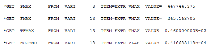
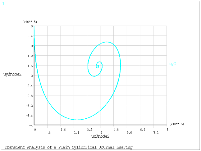
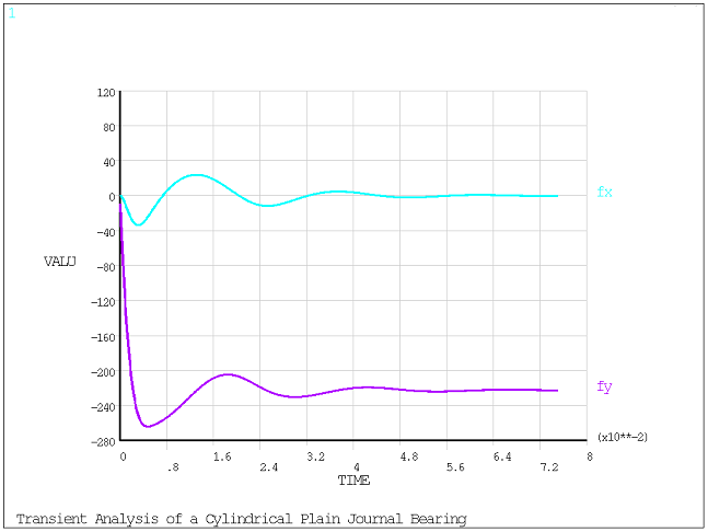
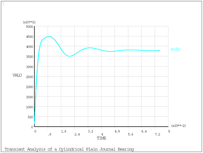
This simple model is a plain cylindrical journal bearing supporting a point mass which represents a rotor. The 22.68 kg rotor is subjected to gravity and rotates at 4000 RPM. A transient analysis is performed for the first 5 rotational cycles (0.075 s). The maximum pressure in the bearing and the maximum amplitude of the bearing force are calculated and the rotor orbit is plotted.
The bearing properties are as follows:
| Clearance: 1.27 x 10⁻⁴ (5 Mils) |
| Length: 0.0254 m (1 inch) |
| Radius: 0.0254 m (1 inch) |
| Viscosity: 6.89 x 10⁻² Pa·s (1 x 10⁻⁵ Reyns) |
/title, Transient Analysis of a Plain Cylindrical Journal Bearing

! ** Rotor parameters
mass = 22.68
pi     = 4*atan(1)
omegaj = 4000*pi/30

! ** Bearing parameters
xclear = 1.27e-4
length = 0.0254
radius = 0.0254

mu = 6.89e-2

! ** Transient analysis parameters
nbcyc = 5
tend  = nbcyc*2*pi/omegaj
dt = 1e-4

/prep7

! ** Nodes
n, 1,  0
n, 2,  0
n, 3,  0

! ** Elements
et, 1, 21
r, 1, mass, mass, mass

et, 2, 214
keyopt,2,1, 2         ! Reynolds integration
r, 2, xclear, length, radius

! ** Material
mp,visc,2, mu

! ** Mesh
type,1
real,1
e, 2

type,2
real,2
mat,2
e, 1, 2, 3

! ** Boundary conditions
d, all, all, 0.0
ddel, 2, UX
ddel, 2, UY
fini

! ** Transient Analysis
/solu
antype, transient
nlgeom,on
acel,, 9.81
d, 2, OMGZ, omegaj
deltim, dt
time, tend
outres,all,all
solve
fini

/post26
numvar,20
nsol,2,2,u,x,ux2
nsol,3,2,u,y,uy2

esol,6,2,2,SMISC,1,fx
esol,7,2,2,SMISC,2,fy

esol,8,2,2,NMISC,3,mofp

prod,10,6,6,,fx_2
prod,11,7,7,,fy_2
add,12,10,11,,fx_2+fy_2
sqrt,13,12,,,fampl

prod,15,2,2,,ux2_2
prod,16,3,3,,uy2_2
add,17,15,16,,ux2_2+uy2_2
sqrt,18,17,,,ecc

extrem

*get,pmax,vari,8,extrem,vmax
*get,fmax,vari,13,extrem,vmax
*get,tfmax,vari,13,extrem,tmax
*get,eccend,vari,18,extrem,vlast

/show,png,rev
xvar,2
/axlab,x,ux@node2
/axlab,y,uy@node2
plvar,3
/reset
xvar,0
plvar,6,7
plvar,8

finish