

The following topics are available:
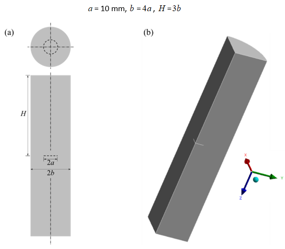
This benchmark problem demonstrates a SMART-based fatigue crack-growth analysis under initial stress. The model is a round tensile bar specimen with an internal circular crack. The initial-stress load is equivalent to a tensile load.
The round bar model has the following geometry parameters:
The material is assumed to be isotropic linear-elastic with the following properties:
| Property | Parameter | Value | Unit |
|---|---|---|---|
| Elastic modulus |

| 200 | GPa |
| Poisson's ratio |

| 0.3 | -- |
| Paris’ law constants |

| 10-10 | (mm/cycle) / (MPa - mm0.5)2.1 |

| 2.1 | -- |
A cyclic far-field tensile load is assumed in the form of normal tractions
( ) at the top and bottom faces:

The reference stress-intensity factor (SIF) for
crack size  is given by:[6]

where:

|
 |
The superposition principle is often used to estimate the SIF under various loading
conditions. On applying the superposition principle, we can infer that the SIF for the given
model under the far-field traction is same as that under the equivalent crack-face-pressure or under the
equivalent initial-stress load:
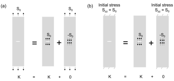
Instead of using the traction load, the problem is solved by applying the equivalent initial stress (INISTATE):

Fatigue crack-growth is analyzed in the quarter-model (shown in Figure 14: Full-Geometry (a) and Quarter-Geometry (b) Model).
The mesh is created in Mechanical APDL using SOLID187 elements:
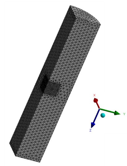
The model is then saved and imported into Ansys Mechanical as an external model for the analysis.
The crack front is specified as a premeshed crack. The element size near the crack front is 2 mm. The total number of elements and nodes are 39756 and 57077, respectively.
The initial-stress load ( ) is applied (INISTATE) via a command snippet.
The top and bottom faces of the model are constrained in the z direction. Appropriate symmetry boundary conditions are imposed on the adjoining flat faces.
The crack-growth is based on stress-intensity-factors (SIFS) calculations. The stress ratio is set to 0.2. The analysis occurs over 10 substeps.
The solution units are based on the Metric system (mm,N).
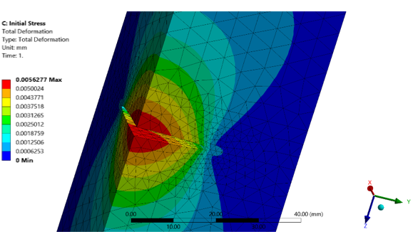
For the specified load and boundary conditions, mode I fracture is induced. Crack extension occurs at each substep.
The total deformation at the last substep shows symmetrical opening of the crack, indicating mode I fracture:
As shown in the plot of the mode I SIF (K1) at the last substep, fracture parameter is almost constant (varying within 1 percent) along the crack front, as expected:
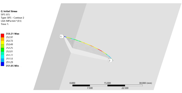
Each crack extension is accompanied by remeshing near the crack front. For the solution, the program converts initial stresses to initial strains at the first substep, and the fracture parameter calculations include the corresponding initial strains. The initial strains are mapped from the old mesh to the new mesh during the crack-growth.
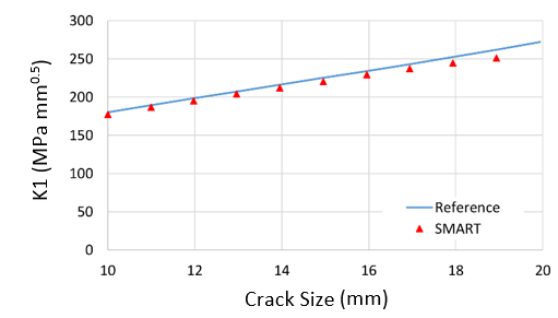
K1 at the crack front is plotted at each substep and its variation with crack size is satisfactorily close (within 4 percent) to the reference solution:
The number of load cycles calculated also matches the reference results closely:
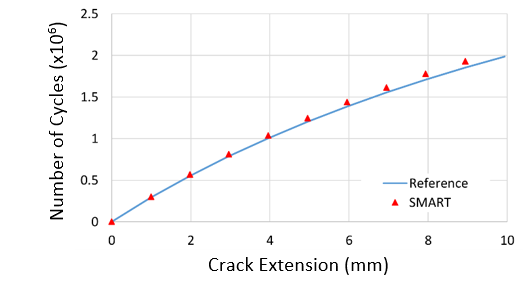
The solution showcases the ability of the SMART-based crack-growth analysis method to solve a fatigue crack-growth problem subject to an initial stress load.
The following files are available for running this benchmark in Ansys Mechanical (.wbpz) and Mechanical APDL (.dat):
[6] Tada, H., Paris, P. & Irwin, G. (2000). The Stress Analysis of Cracks Handbook. 3rd ed. ASME Press.