The following elements and materials/loads support fracture-parameter calculation:
Table 2.1: Element Support for Fracture-Parameter Calculation
| Element Type | Description | Parameter Calculations Supported | ||||||
|---|---|---|---|---|---|---|---|---|
|
2D 4-Node Structural Solid | ||||||||
|
2D 8-Node or 6-Node Structural Solid | ||||||||
|
3D 8-Node Structural Solid |
| |||||||
|
3D 20-Node Structural Solid | ||||||||
|
3D 10-Node Tetrahedral Structural Solid |
| |||||||
|
3D 4-Node Tetrahedral Structural Solid with Nodal Pressures |
|
Table 2.2: Material and Load Support for Fracture-Parameter Calculation
| Fracture Parameter | Material Models Supported | Load Types Supported | |
|---|---|---|---|
| FEM | J-integral |
| |
| Stress-intensity factors |
| ||
| T-stress |
|
| |
| C*-integral |
|
| |
| VCCT |
|
| |
| Material force |
|
| |
| Singularity-Based XFEM | J-integral |
|
|
| Stress-intensity factors |
|
| |
| T-stress | Not available | -- | |
| C*-integral | -- | ||
| VCCT | -- | ||
| Material force | -- |
[a] Includes gravity and centrifugal body forces with commands ACEL, OMEGA, CMOMEGA, CMACEL, CGLOC, CGOMGA. For information about applying gravity and centrifugal body forces, see the documentation for those commands.
[b] The program transforms initial stresses internally to initial strains for fracture-parameter calculation.
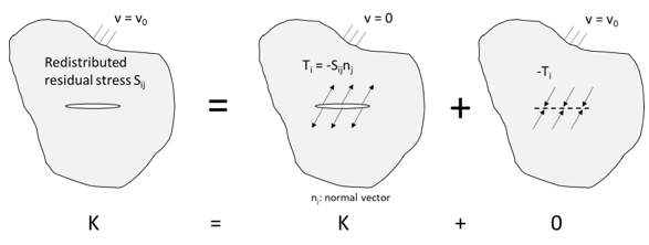
[c] An alternate approach to incorporate any residual (initial) stress for fracture analysis. The program automatically applies a crack-surface traction load equivalent to the specified initial-stress field. Figure 2.2: Superposition Principle: Initial Stress vs. Crack-Face Traction establishes that an equivalent crack-surface traction load leads to the same fracture parameters in the linear elastic regime. See CINT,CSFL for more information.


