


A fracture analysis is a combination of stress analysis and fracture-mechanics parameter calculation. The stress analysis is a standard linear elastic or nonlinear elastic plastic analysis.
Because high stress gradients exist in the region around the crack tip, the finite element modeling of a component containing a crack requires special attention in that region.
The 2D and 3D representations of the region around the crack tip and the terminology used is outlined in the following section. The edge or tip of the crack is referred to as a crack tip in a 2D model and crack front in a 3D model, as illustrated in Figure 1.5: Crack Tip and Crack Front.

The following additional topics related to solving fracture problems are available :
Stress and deformation fields around the crack tip generally have high gradients. The precise nature of these fields depends on the material, geometry, and other factors. To capture the rapidly varying stress and deformation fields, use a refined mesh in the region around the crack tip.
Most of the fracture parameters described in How the Fracture Parameters Are Evaluated are evaluated based on a domain integral approach, which requires that the mesh be well-structured. Typically, radial meshes (in 2D analysis) around the crack tip or cylindrical meshes (in 3D analysis) around the crack front are used so that the fracture parameters can be evaluated accurately.
In some cases, only unstructured meshes or tetrahedral meshes (in 3D) can be used in the crack tip (front) regions, so the unstructured mesh method (UMM) is used to calculate the fracture parameters.
The following additional topics for modeling the crack-tip region are available:
The recommended element type for a 2D fracture model is PLANE183, the 8-node quadratic solid.
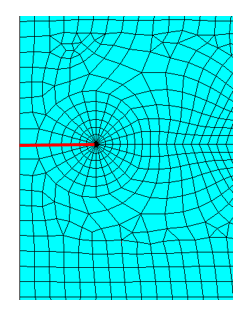
For reasonable results, the first row of elements around the crack tip should
have a radius of approximately a / 8 or smaller,
where a is the crack length. In the circumferential
direction, approximately one element every 15° to 30° is
recommended.
Take advantage of symmetry where possible. In many cases, it is necessary to model only one-half of the crack region, with symmetry or antisymmetry boundary conditions:

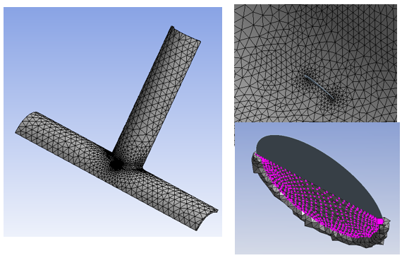
Generating a 3D fracture model is not a trivial exercise. Ansys Mechanical provides ease-of-use tools enabling you to create structured hexahedral meshes for semi-elliptical cracks. For arbitrary cracks, tetrahedral elements are used to mesh the near crack-tip (front) region. Also, Ansys Mechanical offers a variety of controls for meshing the region around the crack front.
This figure shows a mesh generated by Ansys Mechanical in near-region around a semi-elliptical crack in an X joint:
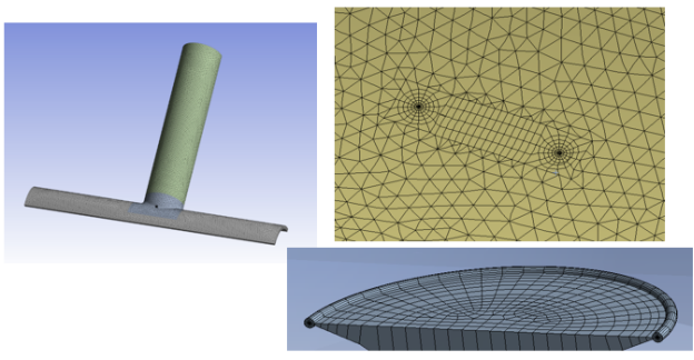
The transitions from structured hexahedral mesh around the crack front to the region away from the crack tip are smooth and seamless.
This figure shows a mesh of tetrahedral elements generated by Ansys Mechanical in near-region around an arbitrary crack in an X joint:
The following topics for fracture-parameter calculation approaches are available:
For more information, see:
Understanding the Fracture Parameters for a list of available fracture-mechanics parameters.
Fracture-Parameter Calculation Element and Material Support for a list of supported elements, materials, and loads for fracture-parameter calculations.
The domain integral method [5] is used to calculate the following fracture parameters:
The virtual crack-closure technique (VCCT) is used to calculate the following fracture parameter:
The fracture parameters are typically expressed as a line integral. They are expected to be path-independent; that is, the line integral calculated along any closed path (including the crack surfaces and the crack tip) will have the same value.
In the domain integral method, the region in which the integrals are evaluated must be confined to a small area surrounding the crack-tip region. The contours should not touch the boundaries or interfaces, nor should they enclose or intersect other inclusions (such as voids or other cracks).
A line integral is converted to an area (for 2D) or a volume integral (for 3D) and then suitably discretized. The discretized integral is evaluated over several contours surrounding the crack tip, as illustrated in the following figure showing the contour definitions for a 2D problem:
Figure 1.10: Numerical Evaluation of Fracture Parameter Over Contours in a Region Around the Crack Tip
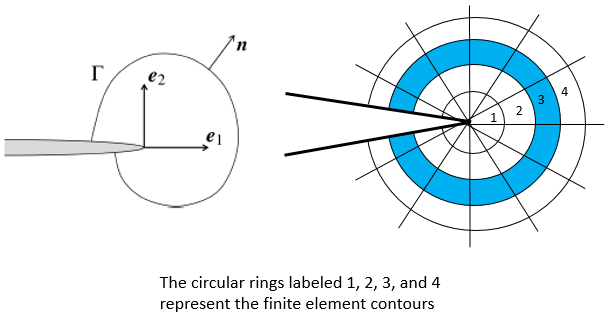
The values of the fracture parameter over the set of contours must be reasonably constant. Use your engineering judgement to evaluate the path-independence of the fracture parameter.
For detailed information about each fracture parameter, see Calculating Fracture Parameters.