


You can create or import a part in SpaceClaim before you begin using Additive Prep, or after, depending on your preferences.
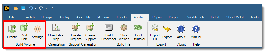
Click the Additive tab to begin using Additive Prep.
If you do not see the Additive tab, check to be sure you have the correct license.
Only one body can be included when you create the Build Volume. If multiple bodies are detected you will see an error message saying "Could not properly import..." Use the Add Part button once the Build Volume is created to add additional parts. See Working with Multiple Parts.
You will need to unlock the part object if it is locked. Locked objects display a tiny lock icon in the Structure tree. Right-click the solid in the Structure tree and select Unlock.
Click Create to establish the Build Volume. Doing so creates new components in the Structure tree. The Build Volume will be empty or will contain your part, depending on whether or not you had a part before you clicked Create.
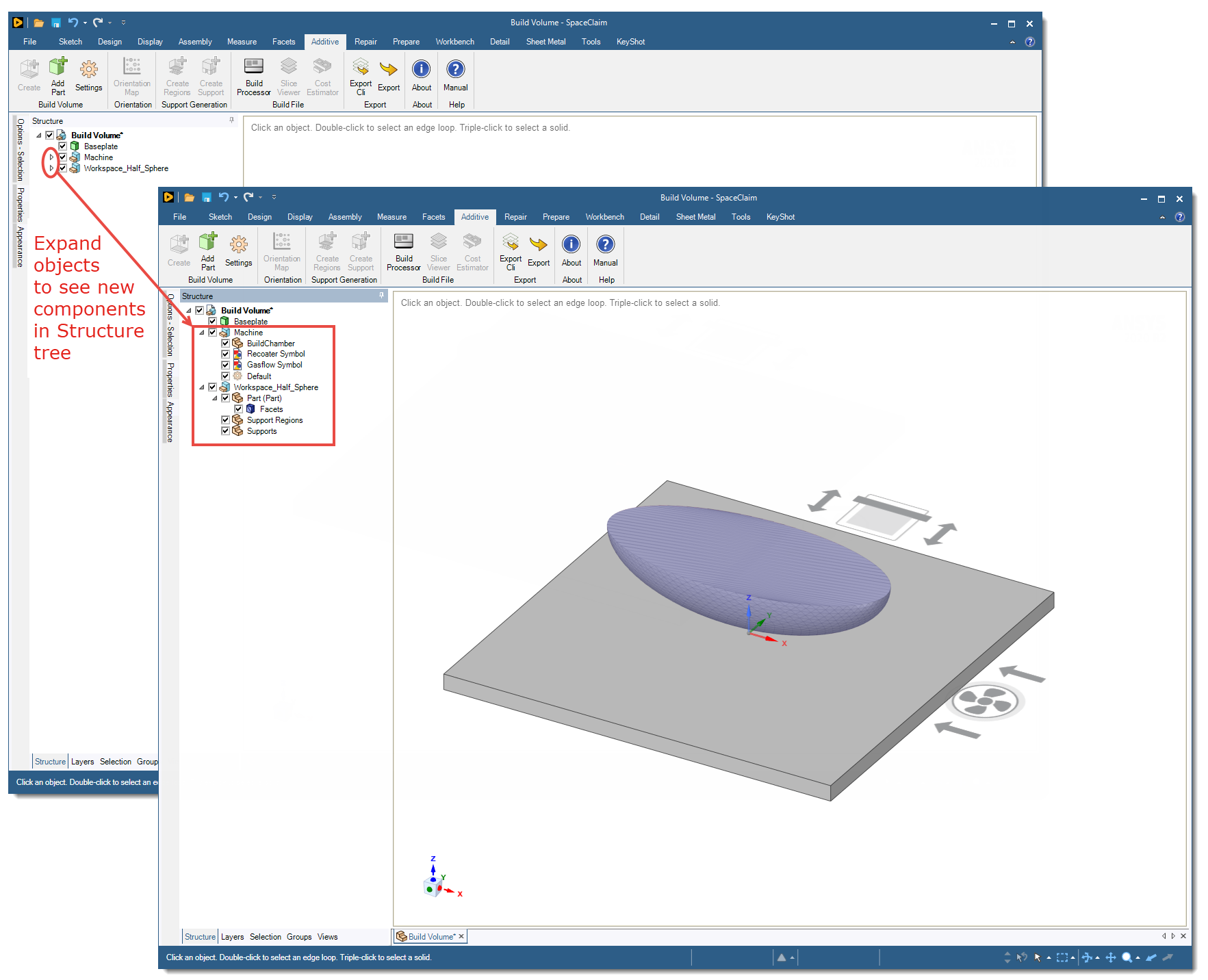
Note: Throughout your use of Additive Prep, as new objects are added to the Structure tree you will need to expand their parent object to see them. This is different behavior than what you might be used to in SpaceClaim.
Build Volume: The overall project assembly including everything listed below:
Baseplate: This is the plate, or build platform, at the bottom of the build chamber. You can adjust the size of the baseplate under Settings > Manage Machines.
Machine: An assembly that holds the machine information.
Recoater Symbol: Shows the direction the recoater travels. This is a fixed symbol only, shown for your reference. You cannot change the recoater direction here. The recoater direction is inherent within the machine you select.
Gasflow Symbol: Shows the direction the gas flows. Gas flow is essential to removing soot from the build chamber. This is a fixed symbol only, shown for your reference. You cannot change the gas flow direction here. The gas flow direction is inherent within the machine you select.
Default (machine name): An object representing your machine configuration. If you already defined a default machine in the SpaceClaim startup options (under Additive Prep Machines), then that machine name is shown here. Click Settings to select a machine other than the default.
Workspace: The assembly consisting of your part, the Support Regions component, and the Supports component for that part:
Part: Your part geometry, which is usually either a faceted part (.stl file) or a SpaceClaim NURBS-based geometry (.scdoc file), sometimes called a design body.
Support Regions component: A component that will hold Support Region objects. Support regions are created using the Create Regions tool under Support Generation in the UI ribbon.
Supports component: A component that will hold Support objects. Supports are created using the Create Support tool under Support Generation in the UI ribbon.
As you add additional parts to the Build Volume, new workspace assemblies will be added.
Click Add Part if you want to add another part to the Build Volume. See Working with Multiple Parts for details.
Click Settings to bring up the Settings panel where you select your machine. See Build Volume Settings for details.
Note: Use the Preserve Original Model Document On Create option to open a new document (a tab at the bottom of the user interface) when you click Create to create the Build Volume. This is a good option when you want to preserve the original part because the design has been approved or certified, for example.
Note: We recommend using a separate session of SpaceClaim for each instance of an Additive Prep Build Volume.