


The functions in the Additive Prep user interface follow a typical workflow. You generally work through the necessary steps for 3D print preparation from left to right and the steps build on each other. You are free to skip certain steps if they are not needed. Similarly, you may revisit previous steps as required.
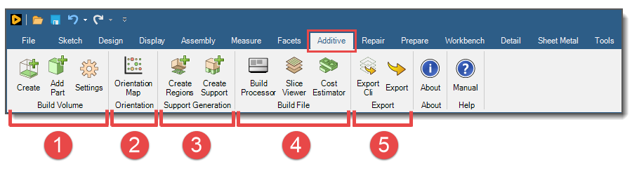
Preparing your build can be done in these steps.
Create Build Volume:
Set up a Build Volume in the Structure tree representing the build chamber that will eventually include a baseplate, your part, and any generated supports.
Add additional parts into the Build Volume, as desired.
Select your machine and material.
Orient Part: Optimally orient your part in the Build Volume using orientation maps that factor in your priorities of build time, volume of supports, and distortion tendency.
Generate Supports:
Once you have oriented your part, create regions that require supports based on overhang angle and region size criteria. Or manually draw your own support regions for more precise control. Support regions are the means by which supports are generated.
Generate supports automatically from the support regions using a combination of several support types with associated parameters.
Generate a Build File:
Use the Build Processor to specify various build process parameters and generate a build file.
Use the Slice Viewer to view and/or animate the progression of laser scan vectors across any slice within the part, or the sequential build of all the 2D slices in the Build Volume.
Run the Cost Estimator to calculate the costs for the build job based on the build file, your material, a profit allowance, and machine-specific costs. The Cost Estimator is limited to only SLM machines at this release.
Export for Simulation or Print: Export the project files for simulation in Additive Print or Mechanical, or for printing directly to a machine.