


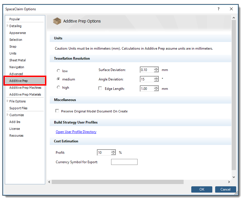
Units
Regardless of whether your part is a design body (.scdoc) or a faceted body (.stl), dimensions of the part must be in units of millimeters (mm) for Additive Prep’s internal calculations. While .stl files are unitless, the SpaceClaim application has to assign a unit system to .stl files for certain functionality to work. If you are creating new geometry in SpaceClaim it will use the units that are set under SpaceClaim Options > Units. This should be set to millimeters if you will be working in Additive Prep. However, there is also an option to override units when saving an .stl file from SpaceClaim. So if you are starting with an existing .stl file, it is possible it may have been saved from SpaceClaim in units other than millimeters. If this is the case, you will need to re-save the .stl file from SpaceClaim in millimeters before bringing it into Additive Prep.
Tessellation Resolution
Here you can set resolution options to control the size and shape of triangular facets in geometries with curvature, used in the calculation of orientation maps and support regions. Remember, Additive Prep will use the existing facets if your original part is a faceted body (.stl). Faceting by Additive Prep is performed only for non-faceted parts. Options include:
Low: lowest resolution—fewest facets created. (Defaults: Surface Deviation = 0.50 mm, Angle Deviation = 25°)
Medium: medium resolution—a medium amount of facets created. (Defaults: Surface Deviation = 0.10 mm, Angle Deviation = 15°)
High: highest resolution—greatest number of facets created. (Defaults: Surface Deviation = 0.01 mm, Angle Deviation = 5°)
The default values of Surface Deviation and Angle Deviation are uniquely defined for each of the low, medium, and high resolution settings. (Notice that the defaults change when you switch from one selection to another.) As soon as you adjust one of the individual settings of Surface Deviation or Angle Deviation, you are customizing the controls for more precise control of the faceting. The control parameters are defined as follows:
Surface Deviation: This is the distance between a chord drawn through a curved cross-section of the model and the curve’s most distal point, in millimeters. It is used as a more global specification. The smaller the value, the lesser the deviation from the actual part surface and the greater the number of resulting facets.
Angle Deviation: This is the angular distance that the chord line makes with a line tangent to the cross-section curve, in degrees. It is used for controlling more localized faceting along curves with small radii compared to the overall part size. The smaller the value, the greater the number of resulting facets.
An additional option may be used as described below:
Edge Length: This is the overall maximum value for facet edges, in millimeters. Note that smaller facet edges may be created. The application attempts to meet your desired edge length setting, but in some design scenarios, may create an edge length that is less than what you specify for Edge Length, to best accommodate the design. This parameter is used to obtain more uniform triangle sizes with better aspect ratios.
Miscellaneous
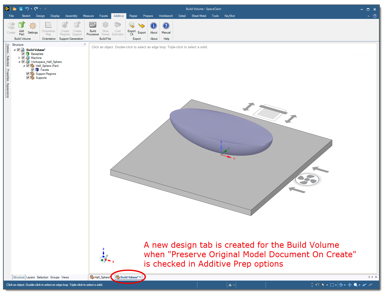
Preserve Original Model Document On Create: Check this box if you want Additive Prep to open a new document (a tab at the bottom of the user interface) when you click Create to create the Build Volume. This is a good option when you want to preserve the original part because the design has been approved or certified, for example. The default (unchecked) uses the existing document when you click Create, such that changes you make in Additive Prep affect the original document. This scenario is necessary for scripting in Ansys Workbench.
Build Strategy User Profiles
Clicking the "Open User Profile Directory" link opens Additive Prep's AppData directory where your custom build strategies are stored. We recommend you do not delete, add, or rename files directly in the file manager accessed from within Additive Prep. If you do, you will need to close the SpaceClaim application and restart in order for those changes to take effect. Rather, you should define new build strategies in the Build Processor.
Cost Estimation
Profit: A built-in profit surcharge based on a percentage of total costs.
Currency Symbol for Export: Symbol to be used in Cost Estimation export file. There is no currency associated with the cost calculations, this field simply allows you to identify a symbol to be used in the report.