


For additive manufacturing Inherent Strain simulations, a special case of nonlinear mesh adaptivity is available in which the total number of elements is reduced by coarsening elements in previously deposited layers. This may help in reducing simulation time in specific cases.
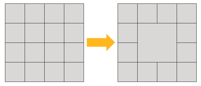
A simple 2D representation of mesh coarsening is shown below, in which four square elements are combined into one larger square element.
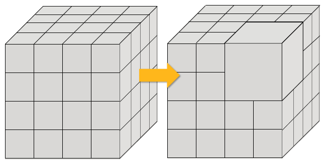
The AM octree method was created specifically for use with laser powder bed fusion simulations, which commonly use cubic (voxelized) elements. The octree method combines eight cubic elements into a new, single cubic element, as shown in this 3D representation.
Nonlinear mesh adaptivity modifies the mesh automatically during the solution based on specified criteria. Mesh modifications occur by general remeshing with the AM octree technique. Loads, boundary conditions, contact conditions, solutions variables, etc., are seamlessly transferred to the new mesh as the solution progresses. Aside from setting the initial criteria, no user action is required.
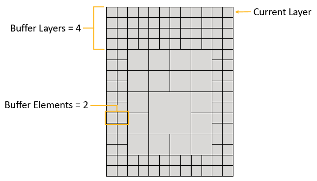
AM octree adaptive meshing criteria include the specification of layers designating when remeshing will start and end, buffer regions, both vertical layers and edge elements, to control where a fine mesh is maintained, and layer frequency to modify how often the program remeshes elements. The figure below shows four buffer layers and two buffer elements.
The goal of AM octree adaptive meshing is to reduce simulation time. However, keep in mind that remeshing takes time, so remeshing too frequently may not provide a simulation time benefit.
Procedural Steps
The AM octree method is a special case of nonlinear mesh adaptivity designed for mesh coarsening. To use AM octree adaptive meshing:
Set up an AM LPBF Inherent Strain simulation in the usual way and be sure to use voxilized meshing (Mesh Method with Method = “Cartesian” and Mesh Using Voxelization = “Yes”).
Apply a Nonlinear Adaptive Region. The Nonlinear Adaptive Region condition enables you to change the mesh during the solution phase. It acts as a remesh controller based on certain criteria. The criteria determine whether or not the mesh will be modified and, if so, when it will be modified and which locations will be modified.
On the Environment context tab: click Conditions > Nonlinear Adaptive Region. (Or, right-click the Static Structural tree object, or anywhere in the geometry window, and select Insert > Nonlinear Adaptive Region.)
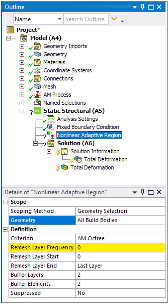
Set remesh criteria:
Scoping will always read All Build Bodies if AM Process is in the project tree, however supports will not be considered for mesh coarsening. Similarly, the base plate is not taken into account.
Criterion: This is set to AM Octree automatically if AM Process is in the project tree.
Remesh Layer Frequency: Frequency with which the program will perform remeshing. A value of 4 will remesh every 4 layers from Remesh Layer Start to Remesh Layer End.
Remesh Layer Start: The layer at which remeshing will start. Value must be greater than or equal to 0.
Remesh Layer End: The layer at which remeshing will end. Value must be greater than or equal to 0. A value of 0 (default) will display “Last Layer” and will continue to remesh through the end of the build.
Buffer Layers: Number of layers to keep at fine mesh resolution between the current, top layer and the layers to be remeshed. Defaults to 2.
Buffer Elements: Number of buffer elements to keep at fine mesh resolution between the part edges and the remeshed elements. Defaults to 2.
For both buffer inputs, higher values may ensure better accuracy, but reduces the number of elements that can be coarsened.
Solve the simulation.
View the coarsened mesh by selecting a result item and then using a section plane to see inside the part. Hint: The best way to see the effect of remeshing is to make a clean, vertical slice through the model.
View the time steps at which remeshing took place by looking for Changed Mesh = Yes in tabular data when a result item or Solution is selected.
Notes on Usage and Known Limitations
Following are considerations and limitations when using AM octree adaptive meshing:
AM octree adaptive meshing is available only for LPBF Inherent Strain simulations. (Because the octree technique is used in the structural solver, it is not available for the thermal portion of a thermal-structural simulation or even the structural step of a thermal-structural simulation where temperature mapping is based on a consistent mesh between the thermal and structural analyses.)
AM octree adaptive meshing is available only with a voxelized mesh (Cartesian mesh with voxelization option).
AM octree adaptive meshing supports models with multiple build bodies as long as the voxel grid between bodies is consistent.
Cubic elements that comprise the part are considered eligible for remeshing. The support, the base plate, and any other non-cubic elements are not taken into account.
Cubic elements with a knockdown factor less than 1, such as those found around edges or in narrow areas that are not completely dense with material, will also not be considered for remeshing.
A simulation can contain multiple nonlinear adaptive regions. This gives you more control and customization over when to remesh, which improves remeshing utilization and could result in significant time savings if used effectively. Consider using a nonlinear adaptive region whenever the build reaches a point where, during a remesh, many elements can be coarsened to maximize time savings. Multiple remeshes can take a significant amount of time, so limiting the number of remeshes to occur in areas where more elements can be coarsened will bring the greatest time savings.
Because AM octree adaptive meshing occurs during solution, the coarsened mesh is visible via section plane only on results displays.
The LPBF High Strain result is not available when using AM octree adaptive meshing.