


Go directly to procedural steps.
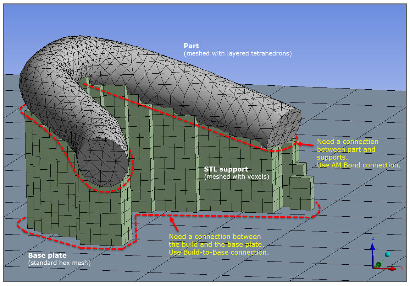
Connections are the mechanism to ensure that the part, support, and base plate bodies in the simulation are aware of each other and are able to share data (temperatures and displacements) across boundaries. Two connection types that are typically used in AM simulations are Build-to-Base contact connection and AM Bond connection.
A Build-to-Base connection is a special case of bonded contact between the element faces on the bottom of the build and the element faces on the top of the base.
An AM Bond connection is used to connect a meshed part to a meshed support when the mesh is non-conformal between them. The internal means of connection is through constraint equations that connect the support nodes to the part elements.
Certain mesh and support combinations in Mechanical result in conformal mesh between the part and the supports, in which connections are automatic by definition of a conformal mesh, while other combinations result in non-conformal mesh. In these scenarios you will need to create a contact connection between them with an AM Bond.
As depicted in the following table, the part mesh/support combinations that are automatic because of the conformal mesh are scenarios C, E, F, J, and K.
The part mesh/support scenarios that require an AM Bond connection are:
When the part and/or the Predefined Support is meshed with layered tetrahedrons (scenarios A, D, G, and H)
When the part is meshed with Cartesian mesh (voxelization option = No) and STL Supports are used (scenario B). STL Supports are automatically meshed with a voxel mesh. In this scenario, we recommend you use the voxelization option to mesh the part instead.
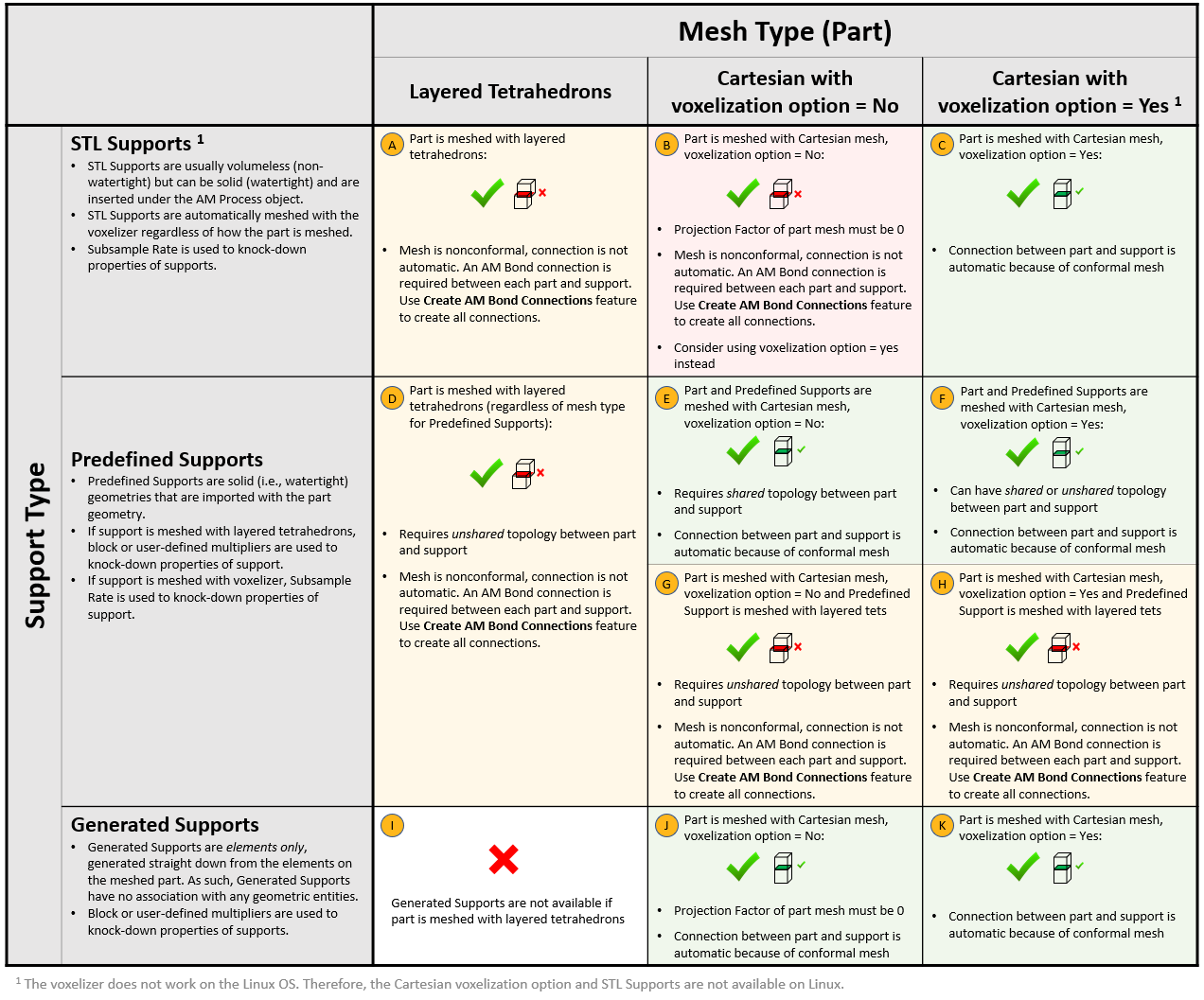
Symbols used in the Mesh and Support Options table are shown here.
 |
This mesh/support combination is available |
 |
This mesh/support combination is not available |
 |
Connection between part and support is automatic because of a conformal mesh |
 |
Contact connection between part and support is required |
Procedural Steps
Defining connections between entities should be performed after they are meshed. For all scenarios, you must define a connection between the build and the base plate so we will start there.
Connection between the build and the base plate — Build-to-Base:
Highlight the AM Process object and then select the Create Build to Base Contact option on the context toolbar.
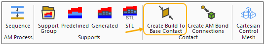
Several things happen. You will see the contact body (red) and target body (blue) views shown in side windows of the Geometry window. The Contact Side is defined as the element faces of the bottom of the build (part and supports). The Target Side is defined as the element faces of the top of the base plate. In the project tree, a Contacts object is added under Connections with a Build to Base object underneath it. Also, named selections have been created that select the element faces at the build-base interface (Build Contact Element Faces and Base Contact Element Faces).
Connections between part and supports — AM Bond:
If you have no supports, or connections are automatic because of a conformal mesh (scenarios C, E, J, and K), skip ahead to the Establish Thermal Analysis Settings (Thermal-Structural System) step.
To create AM Bond connections automatically that will connect all appropriate part and support boundaries, highlight the AM Process object and then select the Create AM Bond Connections option on the context toolbar.
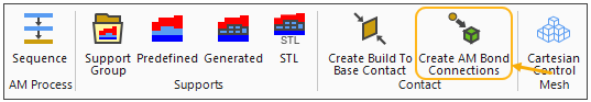
Several things happen. Named selections have been created for the part and support (such as Build Part and STL Support). You will see the contact body (red) and target body (blue) views shown in side windows of the Geometry window. The Contact is defined as the part body. The Target is defined as the support body. In the project tree, an AM Bond object is added to the tree and renamed to reflect the part and support named selections.
The automatic Create AM Bond Connections option described above works to detect appropriate part and support pairs based on proximity to one another. Be sure to review the contact pairs created by examining the views in the Geometry window and the details of the AM Bond objects in the project tree. If there are multiple parts and/or multiple supports closely packed together on a base plate, it is possible the Create AM Bond Connections action results in incorrect pairings. If you suspect that happened, delete the connections and named selections and create AM Bond contact connections manually, as follows.
To manually create an AM Bond connection that will connect a part to a support:
Create a named selection for the part: Right-click the part geometry and choose Create Named Selection. Enter a name for the part geometry and click OK.
Create a named selection for the support:
For an STL support, right-click the STL Support object and choose Create Named Selection of Generated Elements.
For a predefined support, right-click the support geometry and choose Create Named Selection. Enter a name for the part geometry and click OK.
Right-click Connections and choose Insert > AM Bond. Using named selection as the scoping method, choose the part named selection as the Contact, and choose the support named selection as the Target.
Consider the following guidelines for AM Bond connections:
Do not use an AM Bond connection to connect a part or support to the base plate. Use the Build-to-Base connection for that.
One AM Bond connection is required for each part/support combination.
Only one body should be selected when creating the named selection for the part.
The identification of contact and target entities as indicated in step 3 above is appropriate for most cases. Reversing the entities identified as contact and target will not only produce a warning message, but will typically produce unexpected and unrealistic deformation. However, if the support mesh is much coarser than the part mesh, say greater than 2:1 proportions, reverse the scoping selection and make the support the contact and the part the target. This is easily done by right-clicking AM Bond and choosing .
The internal constraint equations used to implement AM Bond connections are applied to the nodes of only the top and bottom of the supports. This means the connections will be in the Z-direction but not the side-to-side directions.
The constraint equations will couple the voxel supports to the meshed body even if there is penetration of the support into the part, such as when positive intrusion values are used when generating volumeless supports. You may, though, see anomalies at some of these interfaces, such as temperature higher than melt or lower than ambient, or very localized large displacements at a support-part interface. The overall solution (temperatures, displacements, and stresses) over the build is good and these local anomalies may be ignored.
You can check the number of constraint equations that are created for each AM Bond connection by viewing the solver output. Under the Transient Thermal system, Solution object, click Solution Information. In Details view, Solution Information, choose Solver Output. In the worksheet window shown, search on "CE connections."