New Element Sets can be manually defined by selecting individual elements. Element Sets store the element labels and are therefore not associated with the geometry. If the mesh changes, the element numbering changes and the element set must be redefined to avoid erroneous lay-ups.
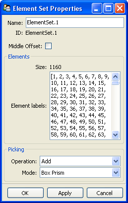
Middle Offset: If the mesh is generated at the mid-plane surface, activate this option such that the section definition is translated to where the middle of the section corresponds to the element. The lay-up definition - in particular the definition of Oriented Selection Sets - is not influenced. Solid Model extrusion and Draping Offset Correction do not support the Middle Offset setting. To verify a lay-up with Middle Offset, use a Section Cut or Sampling Point.
Operation: Add or Remove elements in the list.
Mode: Define the selection mode by dragging the mouse from one corner to the other.
Box on Surface: Only visible elements are selected.
Box Prism: All elements included in the box are selected, depth included.
Point: Element at the picking location is selected.
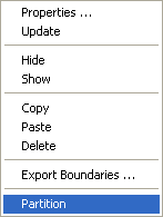
Several options are available in the Element Set context menu:
Properties: Open the Element Set property window.
Update: Update any changes into the database
Hide/Show: Hide or show this Element Set. The elements of the hidden Element Sets are no longer visible in the Scene.
Copy: Copy the selected Element Set to the clipboard.
Paste: Paste an Element Set from the clipboard.
Delete: Delete the selected Element Set
Export Boundaries: Export the boundaries of the Element Set to a STEP or an IGES file
Partition: Create partitioned Element Sets for any Element Set that can be divided in different zones, due to a geometrical separation (for example, three elements share the same edge).