This section gives an overview of how the edge tapering feature works. The Taper Edges option can be applied to modeling plies. Its definition requires a constant taper angle along an edge set. Optionally, a taper offset can be specified. Based on this definition, a virtual taper plane is evaluated to taper the thickness of plies. The effective tapering or thickness distribution over the taper is further dependent on the resolution of the mesh.
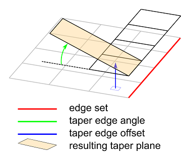
Figure 3.14: Simple Edge Tapering shows a schematic of a simple edge tapering. An Edge Set runs along the side of a square of elements. Ply tapering is evaluated at each element along the edge set. The taper edge offset specifies the normal (thus out-of-plane) distance from each element adjacent to the element set. This offset forms a plane parallel to the underlying element. The taper angle specifies the angle between this offset plane and the resulting taper plane. In the figure, the resulting taper plane is the same for the whole edge set. The resulting taper planes are oriented differently if the Edge Set follows a curved path. The offset direction is set to be positive in the orientation direction of the oriented selection set of the modeling ply. Depending on the mesh and application, it may have to be specified as a negative value.