Geometries can be used to build complex lay-ups during preprocessing in ACP. For example, core of variable thickness can be modeled as a ply whose thickness is set by an imported geometry of the core. Cut-Off Rules can be based on geometry, therefore controlling the lay-up by a CAD surface or at a pre-defined offset to a CAD surface. Geometries are particularly helpful in generating solid models where geometry-based Extrusion Guides, Snap-To and Cut-Off operations can create intricate shapes.
For more information on the use of geometries in a lay-up definition, see the following sections:
Ply thickness definition in Modeling Groups
Extrusion Guides, Snap-To and Cut-Off Geometries in Solid Models
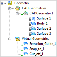
CAD geometries are incorporated in an ACP model by creating a link to a Geometry in the Workbench Project Schematic or by directly importing an external geometry (IGES or STP format). These CAD geometries may be surfaces, bodies, or assemblies of parts. The concept of virtual geometries allows you to select and group specific regions or bodies of the imported CAD geometry and use them for subsequent modeling operations. All geometry-based operations are based on virtual geometries. Virtual geometries act as a reference to one of more faces or bodies of one CAD geometry.
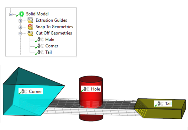
Note: Typically, operations based on CAD geometries are computationally intensive, so it is important to define your geometries efficiently. For example, it is much more efficient to have multiple small geometrical operations rather than a single large one. Small geometries process faster because ACP, prior to running the calculation, filters out all extraneous points and elements. The figure below illustrates three smaller Cut-Off geometries defined instead of one large one. The principle also applies to all other operations based on geometry.