When importing an HDF5 Composite CAE, you must have a model already loaded in ACP. This is because ACP will take the lay-up definitions from the HDF5 Composite CAE and apply them to the model as explained in the next section.
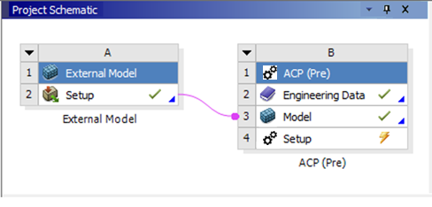
When using ACP within Workbench, the model of the upstream Mechanical component is automatically loaded in ACP as described in Basic Workflow. You can use the External Model component in Workbench to import an external mesh model of almost any format, and then you can transfer it to ACP as shown here.
If ACP runs in standalone mode, you can load a mesh model from a .cdb file (Mechanical APDL format) as shown in Figure 1.45: Switch Between ACP Pre and Post which you will find in the section Workflow in Stand Alone Operation. It is important to understand, the mesh(es) from a HDF5 Composite CAE cannot be loaded directly as a model.
Furthermore, when using ACP within Workbench, materials are not directly imported into ACP because materials are always loaded from Engineering Data. This can cause a newly generated Fabric to lose the link to its material if no material with a matching name exists in Engineering Data. Here is a workaround:
First, extract the materials from the HDF5 Composite CAE file as explained in the section, Extract Materials From Composite CAE H5.
Then import the generated MatML file into Engineering Data.
Finally, import the HDF5 Composite CAE file into ACP.
Another option is to add the materials to Engineering Data manually. You can use HDF View (a third-party application) to open the HDF5 Composite CAE file and look up the material names.
The HDF5 Composite CAE Import supports two types of projections. The first one maps lay-up data onto the shell mesh (reference surface) in ACP. The second option directly converts the ply data from the Composite CAE H5 into Imported Plies Objects in ACP. Below is a more detailed explanation of each projection type.
Mapping onto The Reference Surface
During the import process, the mapping algorithm in ACP begins by computing the ply extent with respect to the reference surface in ACP. It then maps the fiber directions, thicknesses, and other properties onto the surface. Ply material information gets transferred to the Material Data object in ACP, and Oriented Selection Sets are generated based on ply coverage. Finally, thickness distributions and reference direction fields are stored in Look-Up Tables which are then used to define the modeling plies in the lay-up reconstruction.
A ply in the Composite CAE H5 has its own mesh that typically differs from the reference surface in ACP, requiring an adjustment to the mapping parameters. For example, different mesh sizes on curved surfaces can cause element normals to deviate. Nodal locations in the out-of-plane and in-plane directions can also vary, depending on mesh sizing
You can manage these effects with appropriate import tolerances. Large tolerances can result in mapping issues, especially with convergent meshes, as with a T-joint. If the tolerances are too large, ply boundaries cannot be accurately replicated.
Exposed as 3D Plies (Imported Plies)
Instead of mapping the composite data of the HDF5 Composite CAE onto the reference surface in ACP, the data is directly converted into Imported Ply objects if the projection is set to Expose as 3D Plies. Since each Imported Ply has its own mesh that is independent of the reference surface, the meshes of the HDF5 and Imported Plies are identical.
This enables you to build complex 3D lay-up models in a CAD environment and load it into ACP for detailed analyses.
The remaining data, such as Thicknesses and Reference Direction, are stored in the same manner as the Mapping onto the Reference Surface import option.
Ply material information gets transferred to the Material Data object in ACP. Thickness Distributions and Reference Direction Fields are stored in look-up tables which are then used to define the Imported Plies.
A number of settings and tolerances control the import of the composite model. Refer to the dialog box below and the explanations which follow.
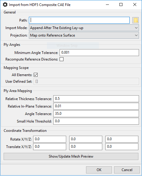
- Path
Specify the path to the .h5 file you wish to import.
- Import Mode
Append: Imported data and objects will be appended to the existing model/lay-up.
Overwrite: Replaces existing objects that have the same id, unless objects are locked. Note: To preserve the ply ordering specified in the HDF5 Composite CAE file, imported plies will be added to the top of the existing lay-up, or moved to the top if they already exist.
- Projection
For additional information on Projection types, see the detailed explanation above.
Map onto Reference Surface: This option maps the plies onto the shell surface in ACP and exposes them as Modeling Plies.
Expose as 3D Plies (Imported Modeling Plies): This option converts the plies into Imported Modeling Plies, uncoupled from the reference surface.
- Ply Angles
Minimum Angle Tolerance: Minimum angle tolerance for which tabular correction angles are computed for plies.
Recompute Reference Directions: When this option is selected, reference directions are recomputed from tabular angle data.
- Mapping Scope
All Elements: By default, the lay-up data specified in the .h5 file is mapped onto all the elements of a reference shell mesh in ACP. Uncheck this Boolean to restrict the lay-up mapping to a user-defined region of interest.
User-Defined Set: The lay-up data is mapped onto the Element Sets specified here.
- Ply Area Mapping
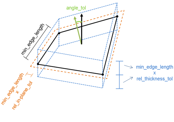
Refer to the Figure below for an illustration of the Tolerance Settings.
Relative Thickness Tolerance: This sets the mapping tolerance in the element thickness direction relative to a minimum element edge length. In the dialog box shown above, assuming a minimum edge length of 1mm, elements will be mapped if their deviation in the element thickness direction is between -0.5 and 0.5 mm.
Relative In-Plane Tolerance: This sets the mapping tolerance in the element in-plane direction relative to a minimum element edge length. In the dialog box shown above, assuming a minimum edge length of 1mm, elements will be mapped if their in-plane coordinates are within the shell mesh with a maximum allowable tolerance of 0.01mm.
Angle Tolerance: Mapping tolerance for angles between element normals (in degrees).
Small Hole Threshold: Holes in plies/Element Sets with an area smaller than this threshold times the area of the Element Set/ply are filled.
- Coordinate Transformation
The imported Composite Definitions are transformed according to the inputs given here. The transformation order is as follows:
Rotation around X-Axis
Rotation around Y-Axis
Rotation around Z-Axis
Translate X, Y, Z
The X, Y and Z rotation happens around three axes of ACP’s global coordinate system. All angles must be specified in degrees.
- Show/Update Mesh Preview
Clicking this button displays a preview of all the meshes in the hdf5 file after the coordinate transformation has been applied.