A composite shell defined using ACP can be imported into Mechanical for analysis by importing the mesh and composite definitions from an upstream ACP system. To import a composite shell from ACP into Mechanical, use the following procedure:
From the Component Systems list, drag and drop an ACP (Pre) system into the Project Schematic. For more information on Component Properties available in Workbench, see ACP Component Properties.
Select the Geometry cell and specify your geometry. Make sure that you properly define your mesh, Named Selections, etc. before opening the geometry in ACP. Note that ACP only uses a linear or quadratic shell mesh.
Select the Setup cell of the ACP system. Right-click the cell and select the option. As needed, activate the Load Model Properties option contained in the Geometry category of the Properties of Schematic. Selecting this property makes your geometry available in ACP's CAD Geometries object.
Perform all of the steps to fully define your ACP (Pre) system.
Return to the Workbench. Drag and drop a supported Mechanical system into the Project Schematic.
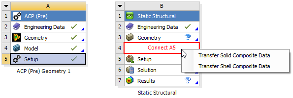
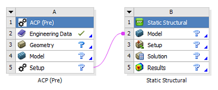
Drag and drop the ACP (Pre) Setup cell onto the Mechanical system Model cell to create a transfer of the model. A context menu gives you options to Transfer Solid Composite Data or Transfer Shell Composite Data. The connection enables the transfer of Mesh, Geometry, Engineering Data, and composite definitions from ACP to Mechanical. When you create this link, the Geometry and Engineering Data cells no longer display for the Mechanical system. ACP provides this system data.
You can change the Transfer Type if you pass the Solid Model to the analysis instead of the Shell Mesh, or vice-versa. See Assembly.
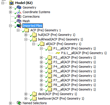
Double-click the Model cell of the Mechanical system. In the Mechanical application, an Imported Plies object is already inserted. Analysis Ply objects, corresponding to the Analysis Plies in ACP, are created under the Imported Plies object.
The Analysis Ply objects are grouped in Production Plies, and Production Plies are further grouped into Modeling Plies to mimic the ply structure defined in ACP:
Perform all the steps to fully define and solve the Mechanical system.
The following should be noted when performing an analysis with imported ACP data:
Since the mesh is imported from an upstream ACP system, any operations that affect the mesh state are blocked inside Mechanical.
It is recommended that you do not edit the mesh inside Mechanical. However, the Clear Generated Data option is available on the Mesh object and performs the action of cleaning up the imported mesh. The Generate Mesh/Update operation restores the imported mesh that was previously modified.
Since the material is assigned to elements/bodies through the upstream ACP system, the Material Assignment field is read-only and set to Composite Material.
If the Setup cell of the upstream ACP system is modified, refreshing the downstream Model re-imports the meshes and resynthesizes the geometry. This action has the following effects:
Any properties set on the bodies imported from the ACP system are reset to default.
For solids, any scoping to geometry (bodies/faces/edges/vertices) is lost and any loads/boundary conditions scoping to geometry are lost.
Tip: Any criterion-based Named Selections defined in the downstream Mechanical system are updated on refresh after any modification in the upstream ACP system. Since criterion-based Named Selections are automatically updated, and any direct scoping is lost, you should create criterion-based Named Selections and then scope any loads or boundary conditions to these Named Selections. This will result in persistence of scoping during modify/refresh operations.
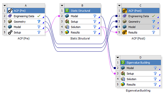
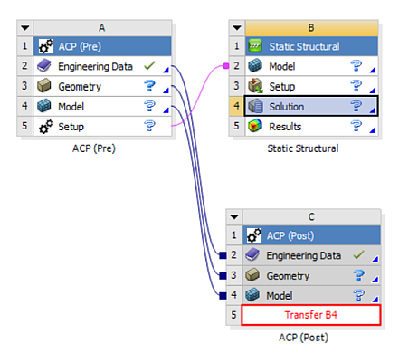
Review the results. Layered results can be reviewed in Mechanical or in ACP-Post. For postprocessing in Mechanical, see Displaying Surface Body Results (including Layered Shell Results) and the Composite Failure Tool. To utilize additional postprocessing capabilities within the ACP application, drag an ACP (Post) system onto the ACP (Pre) Model cell, and connect the Solution cell of the Mechanical system onto the ACP (Post) Results cell.

Analyses that require upstream results from Eigenvalue Buckling or Pre-Stress Modal analyses are also supported and can be transferred from the solution.