


Only the effective lay-up in ACP is extracted during the HDF5 Composite CAE export. This means, for example, ACP will export the ply's thickness distribution but not the taper definitions that affect the ply's thickness. Neither will it export the reference shell surface. It will, however, extract Information on the ply's material, coverage, dimensions, thickness distribution, reference direction field, as well as the overall ply sequencing. All this information gets stored in the .H5 file.
You can then import the extracted data into a program such as FiberSIM for further design and production management.
For Export Settings, refer to the dialog box below and the explanations which follow.
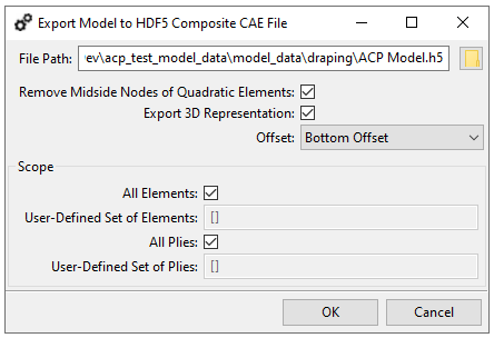
File Path: Specify the destination file name and file path.
Remove Midside Nodes of Quadratic Elements: By default, midside nodes of the quadratic elements are not exported.
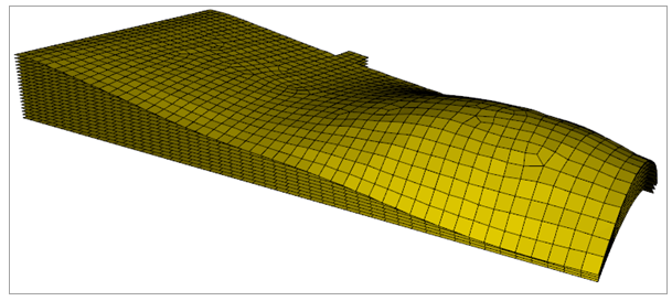
Export 3D Representation: If enabled, a 3D representation of the ply surfaces (including the offsets from the reference surface) and is computed and exported. (An example is shown in the figure below.) The reference surface, the stacking sequence, and the ply thicknesses of the other plies in the laminate determines the exact 3D location of the ply surface. If Export 3D Representation is not enabled, the ply geometry is based on the reference surface only.
Note: If you intend to import the HDF5 Composite CAE file into an external application, you must verify which representation it requires. The standard representation is shell surface, in which case you should not enable Export 3D Representation.
Offset: Select the surface for export: the bottom, mid, or top surface of the plies. The default is Bottom Offset. The Offset option is available only when Export 3D Representation is enabled.
Scope:
All Elements: Uncheck this option to restrict the lay-up export to a region of interest.
User Defined Set of Elements: Here you can limit the exported plies to the specific Element Sets and/or Oriented Element Sets that interest you.
All Plies: By default, all plies of the scope are exported. Uncheck this option to select a user-defined set of plies to be exported.
User Defined Set of Plies: Specify the set of Modeling Plies and/or Modeling Groups to be exported.
Limitation: The 3D lay-up representation cannot be generated for complex shapes and topologies. In those cases, it can help to export sub-areas only by using the user-defined set of elements and user-defined set of plies options in the export dialog. See Figure 2.177: HDF5 Composite CAE File Export Settings.