


An Imported Modeling Ply represents a single ply with a 3D surface mesh which is independent of the reference surface. This allows you to model thick and/or complex 3D laminates in ACP based on separate ply geometries. The Imported Modeling Ply can be used in combination with an Imported Solid Model (lay-up mapping). The section 3D Ply Workflow - Imported Plies in chapter four provides a sample workflow and instructions on how to work with Imported Plies.
The table below lists the key differences between a standard Modeling Ply and an Imported Modeling Ply:
Table 2.1: Key Differences Between a Modeling Ply and Imported Modeling Ply
| Modeling Ply | Imported Modeling Ply | |
| Mesh and Extension | Scoped to the shell reference surface | Holds its own imported mesh (surface) that is independent of the reference surface |
| Orientation | The lay-up orientation is defined by Oriented Selection Sets | The orientation is defined by the element normals of the imported mesh and the offset type (bottom, middle, or top) |
| Reference Direction | The reference directions of the ply are defined by Oriented Selection Sets | Supports the same features as an Oriented Selection Set, but the definition is part of the Imported Modeling Ply object |
| Material | Supports Fabrics, Stackups and Sub-Laminates | Supports Fabrics only |
| Shell Model / Analysis | Contributes to the shell lay-up | Is ignored in any shell analysis |
| Solid Model Extrusion | Considered in the standard Solid Model feature | The standard solid model extrusion ignores imported plies |
| Imported Solid Model / Lay-Up Mapping | Considered in the lay-up mapping of the Imported Solid Model if the scope is set to Element Sets | Considered in the lay-up mapping of the Imported Solid Model if the scope is set to Use Imported Plies |
The context menu of an Imported Modeling Ply contains these actions:
Properties: Display the ply properties dialog.
Update: Update the model until this ply is up-to-date.
Active/Inactive: Choose whether an Imported Ply is active or suppressed in all subsequent analyses.
Copy: Copy into the clipboard.
Paste: Create a new Imported Modeling Ply by copying the object in the clipboard.
Delete: Delete the selected ply.
Standard features in ACP are used to define the thickness distribution, reference and fiber directions. An Imported Modeling Ply contains the properties listed below. Since the meaning is often identical if compared with an Oriented Selection Set or Modeling Ply, it is classified with the same wording.
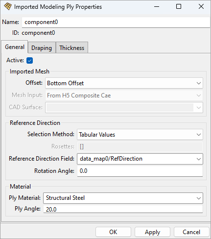
General Properties
Refer to the figure below, General Properties Options.
Offset: Determines if the surface mesh defines the bottom, mid or top surface of the ply.
Mesh Input: Indicates whether the mesh was imported from a HDF5 Composite CAE or from a CAD geometry. This is automatically set by the application based on the input source and is therefore read-only.
CAD Surface: If the Mesh Input is From Geometry, then the selected Virtual Geometry defines the surface of the ply.
Selection Method: Defines the mapping algorithm for the Rosettes if more than one Rosette is used. For more information, see Reference Direction in the section above, Oriented Selection Sets.
Rosettes: Select which method one or more Rosettes will define the Reference Direction for each element.
Reference Direction Field: Defines the direction column of a 3D Look-Up Table. Only applicable to the tabular values method.
Rotation Angle: Angle (in degrees) to rotate the Reference Direction around the Orientation Direction. For more information, see Use Cases for Rotation Angle.
Ply Material: Select the Fabric that defines the material of the ply and nominal thickness.
Ply Angle: Set the design angle between the reference direction and the ply fiber direction.
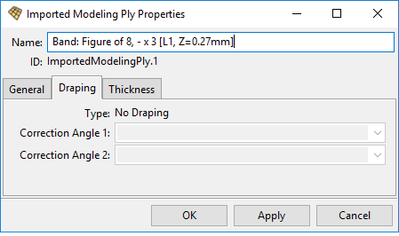
Draping Properties
Refer to the figure below, Draping Properties Options.
Type: Specifies the type of draping
No draping: Constant thickness defined by the Fabric
Tabular values: Variable thickness by mapping a LookUp Table field
Correction Angle 1: Sets the draped fiber direction
Correction Angle 2: Sets the draped transverse direction
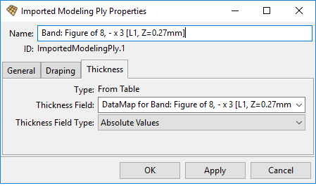
Thickness Properties
Refer to the figure below, Thickness Properties Options.
Type: Thickness definition method
Nominal: The thickness defined in Fabrics is used for the thickness definition.
From Table: A data field evaluates the thickness. ACP interpolates or extrapolates the thicknesses for each element.
Thickness Field: Thickness is determined by mapping the selected LookUp Table Column to the mesh.
Thickness Field Type:
Absolute Values: Values in the Look-Up Table define the thickness.
Relative Scaling Values: Values in the Look-Up Table are scaling factors.
Limitations
StackUps and Sublaminates are not supported as ply material.
The ACP model always needs a reference surface, even if it is not relevant in the lay-up mapping (Imported Solid Model) workflow in combination with Imported Plies.
The CAD geometry must be a surface. Solid geometries are not supported.
Export Composite Definitions to ACP File … does not support Imported Ply objects
The Excel Interface cannot be used in combination with Imported Plies.
The features Sensor and Ply Book do not take Imported Plies into account.
The variable material workflow is not supported. That includes the field definitions and material plots.
The HDF5 Composite CAE Export does not support Imported Plies.