


Creating an Optical Surface
This page shows how to create an optical surface from a parabolic or freeform support.
To create an Optical Surface:
-
From the Design tab, click Optical Surface
_Optical_Surface.png) and select a grid type/shape (Rectangular, Circular, Stripes, Freestyle Rectangular or Freestyle Circular).
and select a grid type/shape (Rectangular, Circular, Stripes, Freestyle Rectangular or Freestyle Circular).
-
In Source, from the Type drop-down list, select:
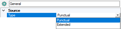
- Punctual to position the source by selecting a point in the 3D view.
- Extended to select an emitting surface like a filament, cylinder, LED, chip etc.
-
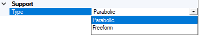
In Support, from the Type drop-down list select which support to use to build the optical surface:
 Important: When computing the Optical Lens, the support is meshed. The bigger the support, the longer the computation of the feature. We recommend you to define a support size as close as possible to the feature size.
-
Select Parabolic to create the parabolic support by defining its origin, axis and orientation or click
_Axis_System_Autofill.png) and select a coordinate
system to autofill the Axis System.Note: If you define manually one axis only, the other axis is automatically (and randomly) calculated by Speos in the 3D view. However, the other axis in the Definition panel may not correspond to the axis in the 3D view. Please refer to the axis in the 3D view.
and select a coordinate
system to autofill the Axis System.Note: If you define manually one axis only, the other axis is automatically (and randomly) calculated by Speos in the 3D view. However, the other axis in the Definition panel may not correspond to the axis in the 3D view. Please refer to the axis in the 3D view. - Select Freeform to build the optical surface on an existing surface. Then, in the 3D view click
_OPD_Support_Surface.png) to select the freeform surface.
Note: A face or a multifaces body can be selected as surface.
to select the freeform surface.
Note: A face or a multifaces body can be selected as surface.
-
-
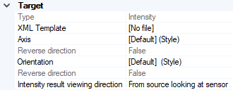
In Target, if you want to verify that your current design passes regulation standards, select a XML Template corresponding to the regulation standard.
The XML template will be used by the Photometry tool simulation to generates the photometric preview displayed in the feature viewer, the HTML report and the XMP file of the selected element(s) of the feature.
Note: You can find existing XML templates of regulation standards in the Ansys Optical Library.For more information on the Photometry tool, refer to Understanding Display Properties.
-
Define the result viewing direction and the position of the observer point:
-
If you want to define specific axes for the sensor, in the 3D view click
_Projection_Axis.png) to select a projection axis and
to select a projection axis and _OPD_Optical_Axis.png) to select an orientation axis or click and select a coordinate
system to autofill the Axis System.
to select an orientation axis or click and select a coordinate
system to autofill the Axis System.
- From the Intensity result viewing direction drop-down list:
- Select From source looking at sensor to position the observer point from where light is emitted.
- Select From sensor looking at source to position the observer in the opposite of light direction.
-
If you want to define specific axes for the sensor, in the 3D view click
-
In Manufacturing, activate the sewing and drafting of the elements if you want mechanical constraints to be taken into account:
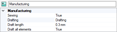
- Activate the Sewing if you want any gaps between elements to be automatically filled.
-
Activate the drafting of the elements if you want mechanical constraints coming from unmolding to be taken into account.
If activated, define a Draft length in mm. The draft length defines the sewing surface created between two adjacent faces.
-
From the Design tab, click Compute
_Compute.png) to generate the surface.
to generate the surface.