


Understanding Display Properties
The viewer and display properties assist the design process by helping to understand the feature behavior.
The viewer gives information about the feature (surface) behavior and characteristics.
In the viewer, different types of informations are displayed according to your configuration of the optical surface.
Several types of elements can be displayed.
Grid
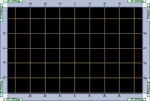 |
| Grid with X Step = 10deg and Y Step = 10deg |
A grid is displayed in the viewer and gives information about the size of the beam.
The grid is defined angularly and the step is expressed in degrees.
Source Images
Source Images is only available with the Extended source type.
The source images give information about the surface behavior inside the target. Their color depend on the group's color of the selected element.
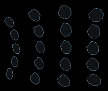 |
| Source Images with U Samples = 5 and V Samples = 4 |
U Samples indicate the number of source images along the first parametric surface direction.
V Samples indicate the number of source images along the second parametric surface direction.
The external face of the elements is discretized according to U Samples and V Samples giving particular points. The image of the extended source is then calculated for each of these particular points using the Snell's law.
The source images are approximated because of the meshing and the extended source convex hull considered for the calculation.
Beam Pattern
A beam pattern is depicted as a grid (a network of lines) and gives information about the beam's shape.
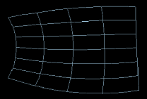 |
| Beam pattern with U Samples = 7 and V Samples = 5 |
U Samples indicate the number of isoparametrics along the first parametric surface direction.
V Samples indicate the number of isoparametrics along the second parametric surface direction.
The external face of the element is discretized according to U Samples and V Samples giving a particular network of lines on this element. The reflection of this network of lines is carried out using the Snell's law from the source point.
The calculation of the beam is calculated considering a punctual source. If an extended source is used, the barycenter of the extended source is considered as the punctual source.
Photometry
Description
The Photometry tool is an integrated simulation that allows you to have a quick preview and result of the selected element(s) of the feature.
When activating the Photometry, the simulation is automatically launched using the GPU Compute functionality and generates a photometric preview displayed in the feature viewer, a HTML report and a XMP file in a folder named as FeatureName_InteractivePhotometry located in the Speos Output Files folder.
Therefore, the Photometry tool allows you to directly iterate during the design process of the Optical Part Design feature in order to reach the regulation standards required, without having to run a Speos simulation that can take times to generate the output results.
_OPD_Optical_Surface_Feature_Viewer.png) |
_OPD_Optical_Surface_XMP_Result_Photometry.png) |
| Photometry of a group of elements from the feature viewer | XMP result of the group of elements selected |
Click Show Regulations to open the HTML report generated.
Simulation Parameters
The Photometry tool simulation needs some information in order to run correctly. Therefore, the simulation considers the following parameters:
- Source Parameters
The simulation considers the Extended source type of the feature definition with a lambertian emission
Note: The Punctual source type is not compatible.- The simulation considers the Flux of the feature definition (100 lm by default).
- Optical Properties of the extended source: the simulation considers by default a Surface Optical Property as a Mirror set to 0% and a Volume Optical Property set to None.
Geometry Parameters
The simulation considers the Optical Part Design feature geometry with the Optical Properties you applied manually.
If you have not set any Optical Properties, the simulation considers by default a Surface Optical Property as a Mirror set to 85%.
Sensor Parameters
The simulation considers the Intensity Target type of the feature definition.
The size of the sensor used corresponds to the defined Beam Pattern parameters of the feature viewer.
Regulation Standards
The simulation considers the XML template selected in the Target definition.
The XML template corresponds to the standard that you want the feature to pass.
Note: You can find existing XML templates of regulation standards in the Ansys Optical Library.
Beam Type Compatibility
The following table describes the compatibility between the beam types and the photometry:
| Beam type | Radii | Freeform | Sharp Cutoff | Flute |
| Compatibility |